As a starting place, for most small electronics soldering, 1/32 inch (.03) rosin-cored, 60/40 (tin-lead) or 63/37 solder should work fine. Rosin-cored lead-free is fine, too. Unless you have reason otherwise, don’t use “no-clean” solder–it’s very likely that you don’t need to clean the regular rosin-cored solder. The solder should be thin enough to prevent accidentally applying too much (and causing a solder bridge), but thick enough so that more doesn’t have to be gathered from the coil too often.
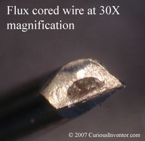
Besides affecting your feed-rate and convenience, the solder thickness also relates to the amount of flux that is delivered. Flux is basically a weak acid that removes oxides so that solder can adhere to the metal, and is so essential to the soldering process that it’s built into the core of common wire-solder. It also helps the solder spread out (reduces surface tension), transfer heat, and acts as a protective blanket to keep oxygen away from the metal until solder displaces it.
For the most part, manufacturers include a sufficient amount of flux in the wire, but if you use an extremely thin wire there may not be enough to clean the joint OR the iron tip. Consider using a thicker gauge for cleaning the tip periodically if you’re using especially thin solder. Liquid flux is helpful for SMD soldering, too.
When picking a wire-solder, there are 4 features to decide on: flux type and amount (% weight), alloy (tin-lead, lead free, silver bearing, etc.), thickness and total amount (1oz, 1lb?).
- Flux:Just what is flux, what kinds are there, and when do I need liquid flux?
Why it’s needed: Solder doesn’t just freeze on a joint, it actually forms a metallurgical bond by dissolving and chemically reacting with the base material. Unfortunately, almost all metals oxidize in air and form an oxidized layer that prevents solder from wetting and bonding to them. What is oxidation?
The main choice to make when deciding on a flux, whether it comes in a cored wire or a liquid or paste form, is how aggressive it should be. The more aggressive or “active” the flux, the harder the oxides it can remove, and the faster it can remove them. Going from weakest to strongest, typical choices for hand soldering applications include: “no clean”, RMA (Rosin Mildly Activated), RA (Rosin Activated), and water soluble. A newer classification system (J-STD-004) has recently been adopted and classifies fluxes not by rosin content, but by activity, material, and halide presence.
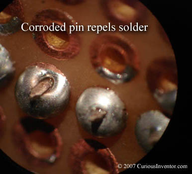
The downside to choosing a more aggressive flux is that the residues left over after soldering MAY be corrosive, conductive, or enable fern-like growths called “dendrites” to grow between connections. A brief description (p.29) of dendrite growth and some great pictures at the end of this paper.
Because of the risk of corrosion and dendrite growth, most manufacturers clean off the residue from RMA and RA fluxes, and some even clean “no-clean” residues. The question of what flux to use and whether / how to clean it is quite involved.
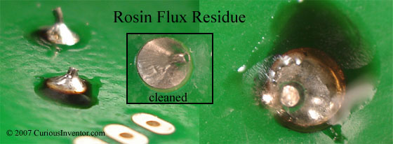
Rosin flux is quite an interesting animal. Made from pine tree sap, at room temperature, it’s an excellent insulator and non-corrosive. When it hits 226 °F it begins to turn acidic and attack oxides, but then when it cools it supposedly leaves residues that are again inert. Kester’s data sheet for “44” flux (classified as RA and ROM1) claims no cleaning whatsoever is necessary. I haven’t read of any manufacturers that would use a RA (or even an RMA) flux and not clean it–the military won’t even use a RA flux WITH cleaning because of the risk that some will be left behind. This Chemtronics author recommends cleaning even the “no-clean” fluxes. He also points out that even if the residue is non-corrosive and non-conductive, it might be tacky and attract dust that causes a short.
To add one more piece to the puzzle, flux generally gets used up during the soldering process. This is why no-clean fluxes are oftentimes ineffectual for lead-free soldering, which can require slightly higher temperatures and longer heating because the lead-free solder “wets” slower. The no-clean flux can burn off before the joint is complete. Alternatively, if you apply liquid flux far from a joint, it may still be active (corrosive) if it never got heated.
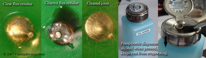
I’m not making missile guidance electronics, I’m making a robot that pours a beer, what flux should I use and do I really need to clean? Even manufacturers of non-life critical electronics have much more stringent reliability requirements than an individual. They must ensure that tens of thousands of products will work for multiple years, not a single project.The safe advice is to use the least aggressive flux that enables solder to quickly wet or cling to the surfaces, and then clean off the residues with alcohol and lint-free wipes (don’t just spread the flux around). Try starting with a rosin-based mildly activated flux: RMA. I am inclined to trust Kester’s spec sheet for “44” (RA) flux that says it does not actually require cleaning. Other flux manufacturers may have RA or RMA level fluxes that do indeed need to be cleaned, so if you don’t know what you’re using, cleaning is probably prudent. If you are going to clean rosin fluxes, do it soon after soldering because they quickly harden (see pics under ‘Cleaning’). Finally, I would personally avoid no-clean fluxes and solder unless you have a critical application and very clean parts.
Lead-free solder generally requires a made-for-lead-free flux designed to be used under slightly higher temperatures.
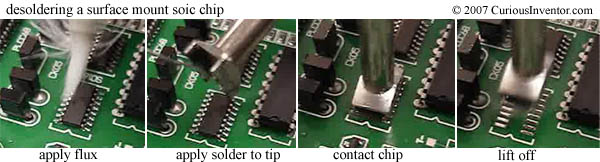
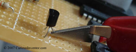
Liquid flux can greatly help with surface mount soldering and desoldering components, but the flux inside cored-solder should be sufficient for through hole components. When soldering SMD components and desoldering pretty much anything, liquid flux acts as a blanket that helps to spread heat and also keep oxygen away from the metals. Finally, flux lowers the surface tension of solder, helping it to spread out and wick into connections.
A water-soluble flux may be necessary for heavily oxidized parts or difficult metals like nickel. Without question, clean these fluxes. Special fluxes and solders exist for aluminum and stainless steel and these also certainly require cleaning. Never use acid-core solder; it deposits zinc chloride into the solder that cannot be cleaned out. A final reason to clean flux residues is if you’d like to apply a conformal coating and aren’t sure whether it will adhere to those residues.
Some more references:
- Never use acid-core and how to solder to stainless steel (Kester)
- White residue and all about rosin (more Kester)
- Good mini-class on fluxes: Bolton University
- To clean or not to clean and a brief history of electronics cleaning: more Bolton
- The Kester catalog provides good info on the solderability and flux requirements of various materials (see p.14).
- Flux residues and what to do about them. This explains a bit about cleaning options and the health risks of rosin and non-rosin fluxes.
- Alloy:60/40, 63/37, tin-lead, lead-free, silver bearing, RoHS, eutectic, oh my…
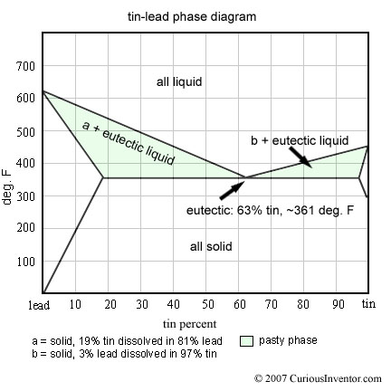
- Standard lead-based solderis made of tin and lead. When you see 60/40 or 63/37, it means 60% tin by weight, 40% lead. Either once of these alloys should be fine for typical small electronics soldering. 63/37 in bulk is slightly more expensive because of additional tin, but has the special property of being a “eutectic” alloy, which transitions from liquid to solid at one temperature (like water) instead of range of temperatures. Basically, in non-eutectic alloys like 60/40, there is a “pasty” region of temperature where portions of the solder are frozen and other portions are liquid. What does this mean for soldering and is 63/37 really that much better?
Alloy metals have some interesting properties that are different from the metals comprising them. In tin-lead solder, the mixture has a lower melting point than either lead or tin alone, and the melting point varies depending on the portions. The mixture that yields the lowest melting point is called eutectic. This is also the only mix where all the constituents melt and freeze at the same temperature.
If the tin-lead alloy isn’t eutectic (ie, if it is not 63% tin), it will go through a “pasty” phase while it freezes. Unlike water, which freezes entirely at 0 °C, some parts of a non-eutectic mixture of tin-lead freeze at higher temperatures than other parts. For a somewhat simplified explanation, if you held the temperature of 60/40 slightly above 361 °F, the “extra lead” would solidify and be floating in a liquid 63/37 eutectic mix. For a more exact and great explanation of this process, look here.
How is it that the mixture of two elements somehow lowers the melting point? And I quote: “increased entropy.” Chew on this. (Another great phase-diagram explanation with a bonus of why ice and salt can get almost 30 °F below freezing–enough to freeze ice cream) And one last great explanation–talks a bit about grain structure and how solder isn’t a simple homogeneous mixture of tin and lead.
This compares the difference between eutectic freezing in tin-lead and eutectic freezing in more complex 3 element lead-free alloys.
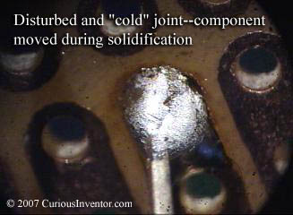
So which is better, 60/40 or 63/37? A decade or so back (before the lead-free movement), most manufacturers incurred about a 5% increase in cost to switch from 60/40 to 63/37. 63/37 flows slightly easier, makes shinier joints, and has a faster total freezing time which means there is less risk the joints will be “distrubed,” which is what happens when the joint moves during solidification. This can lead to internal fractures that cause poor electrical connections and unreliable mechanical joints. Note that 63/37 doesn’t freeze instantly (just like water)–it still has a window of time during which the joint can be disturbed, too.
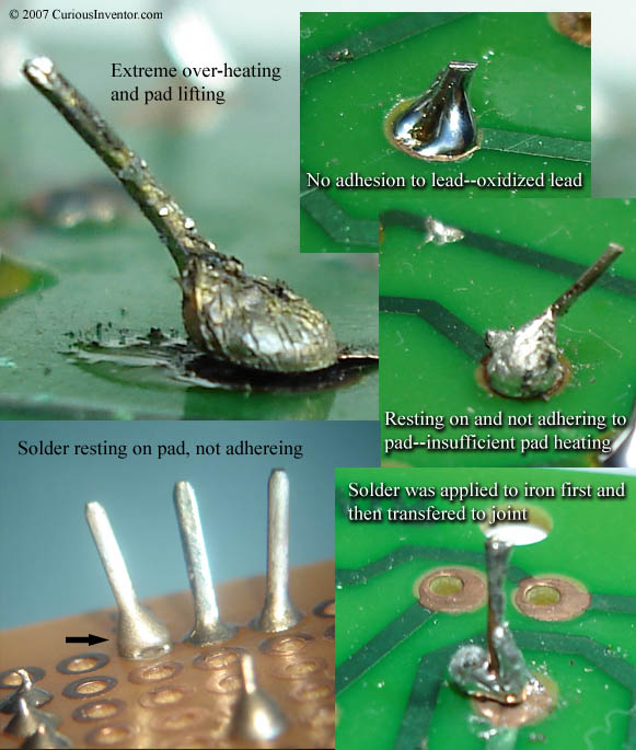
I think most would say that the enhanced properties of 63/37 really only matter for mass soldering operations like wave or reflow soldering, and that there is little difference for hand soldering. A dull joint is more often caused by insufficient heat, dirt or oxides, or lack of flux rather than alloy makeup. (A no-clean flux may burn off before the joint is complete) Holding everything else constant, the difference in shininess between 60/40 and 63/37 is completely cosmetic. If you’d like to see a shiny 60/40 joint, try using Kester 60/40 with #44 flux.
- Silver bearing solder: (that is, contains silver, not for roller bearings) Silver is used in one of the leading alloys for lead free solder (An96.5% Ag3.0% Cu.5%) and also as an addition to tin-lead solder, usually in the 2-4% range (when you se 62/36/2 this means Sn64Pb36Ag2).People claim that it flows better, has a lower melting point, is stronger, and has a higher conductivity. According to Indium’s solder wire data sheet, their 2% silver solder has an electrical conductivity that is 11.9% of Cu compared to 11.5% of 63/37 tin-lead solder, a shear strength of 7540psi vs. 6200psi, and a tensile strength of 7000psi vs. 7500psi for 63/37. So, yes, the claims are true, and also mostly insignificant. Silver was initially added to solder to prevent silver platings on component leads from dissolving into the solder (“silver migration”) and forming brittle joints. Having silver in the solder reduces migration, so you may want to use it on silver joints. (Note: this logic doesn’t entirely make sense to me. If silver getting in the solder caused embrittlement, how does adding more silver prevent this?)
Audiophiles seem to be enamored by 4% silver bearing solder, namely some from WBT, Cardas, and WonderSolder. Are these really better for audio?
- Lead-free Solder: As of July 1st, 2006, European laws mandated that new electronics be almost entirely lead free. As of yet, there are no US laws (outside CA) mandating the removal of lead, but most manufacturers are switching over for competitive reasons. More on RoHS, WEEE, and lead risks:
The most popular lead-free alloy seems to be Tin 96.5% Silver 3.0% Copper .5%. The wiki page on solder mentions several different lead-free varieties.
-AIM lead-free solders.
-Huge list of Indium lead-free solders and their properties.Lead-free solder generally melts at a higher temperature, and doesn’t wet as quickly to metals. (Eutectic tin-lead solder melts at 361 °F and the SnAg3Cu.5 melts at 423 °F.) Manufacturers generally recommend setting soldering iron temperatures between 700-800 °F for lead-free instead of 600-700 °F for tin-lead soldering. The 15 Watt RadioShack® iron I had operated a bit below 500 °F, so soldering should be possible with it, but maybe slow. Technique wise, since lead-free wets slower, joints will take longer (upwards of 4-7 seconds), but this doesn’t mean the soldering iron temperature should be turned up excessively–patience is better than higher temperatures. If you’re going to use a lead-free solder, get a flux that’s designed for the higher temperatures–the regular no-clean fluxes will likely burn off before doing their job.
A quick word on reliability. Some say that lead-free joints are stronger, and while the material is indeed stronger, it’s less flexible than lead-based solder, so expansion and contraction due to temperature change has been shown to break components held by lead-free solder. It seems true mechanical reliability of lead-free vs. lead depends heavily on the situation (see p.30). There is also concern of something called “tin whiskers.” These are extremely thin crystalline growths that grow perpendicularly out from surfaces. These took down some space systems and NASA has a great page here. These are different from dendrites (which grow on the surface) and appear to be more likely on bright all-tin platings. Most component platings used to consist of a tin-lead mixture, and since all-tin platings are a common lead-free replacement, people are concerned. I have yet to find any literature that points to TinSilverCopper solder as a risk factor, though. I believe it is a plating issue, only.
One more link: –Why tin or silver?
- Standard lead-based solderis made of tin and lead. When you see 60/40 or 63/37, it means 60% tin by weight, 40% lead. Either once of these alloys should be fine for typical small electronics soldering. 63/37 in bulk is slightly more expensive because of additional tin, but has the special property of being a “eutectic” alloy, which transitions from liquid to solid at one temperature (like water) instead of range of temperatures. Basically, in non-eutectic alloys like 60/40, there is a “pasty” region of temperature where portions of the solder are frozen and other portions are liquid. What does this mean for soldering and is 63/37 really that much better?
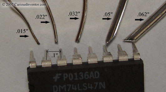
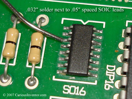
- Thickness and Amount:As a general guide, .032″ thick solder (21 gauge) should be suitable for through hole soldering and some surface mount soldering. For finer pitch surface mount devices, use .02″ or .015″, and if you’re soldering a lot of switch terminals, or tinning thick gauge wire you may want .05″. If you use .015″ solder consider having some thicker solder on hand to re-tin your tip, since the amount of flux in .015″ may not be enough to remove tip oxides. The picture below shows how the various thicknesses compare next to the standard .1″ spaced DIP pins.
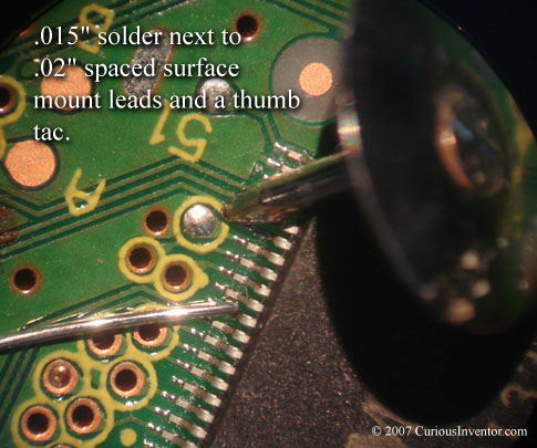
 Expand to see how .032″ and .015″ solder compare to a SOIC surface mount chip and fine pitch (.02″) device.
How much solder do I really need? An ounce? A pound? How long will a pound last?To get a very approximate feel for just how much solder is in an ounce vs. a pound, I measured how much .032″ solder it took to attach ten 16 pin DIPs. Trying to provide an upper bound, the soldering is excessive, and a generous glob was placed on the tip in between each chip to account for solder used to tin and protect the tip during normal use.
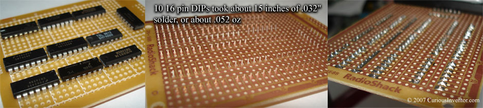
The ten chips took about 15″ of generously applied .032″ solder that weighed in approximately at .052oz. This particular solder weighed about .00348oz/in. At about 3.27e-4 oz/joint, a 1 oz spool should last 3060 joints, a half pound should last 25 thousand joints, and a pound should last about 50 thousand joints. Mileage will certainly vary with different sized solders, joints, tinning wires, and highway vs. city driving, but if you’re not in a production environment, a half pound should last a while.
- Solder Fumes:What is exactly in solder fumes? Am I safer using lead-free solder?
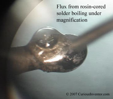 Lead boils at over 3000 °F, and in most cases soldering tips should be kept below 750 °F, so it is highly unlikely that gaseous lead is present in the fumes. The fumes are actually from the flux boiling, which still isn’t great for you–many of the chemicals found in cigarette smoke are found in flux fumes: formaldehyde, toluene, alcohols, and hydrochloric acid to name a few. Most of the public health literature indicates that asthma is the major health risk from soldering fumes (not cancer or lead poisoning). When acquired, it is permanent and can cause hyper sensitivity so that even small amounts of fumes bring on attacks. Surprisingly, scientists have not been able to determine what exactly in the fumes cause the health defects, nor what amounts are harmful. Yet, the British health department has set exposure limits of .05 mg/m^3 over 8 hours and .15 mg/m^3 over 15 minutes. I believe these limits have been shown to provide a safe work environment and also one for which the necessary systems / filters are financially reasonable.
Some informative links:
- Solder Fumes and You A British health department pamphlet explaining the health hazards of rosin-based flux fumes (irritation, headaches, dermatitis, asthma) and what precautions employees and employers should take. Note the total lack of any mentioning of lead poisoning.
- Workplace Exposure to Rosin-based Solder Flux Fume During Hand Soldering A study done by the UK Health and Safety Laboratory measuring exposure levels and also the effectiveness of various exhaust, ventilation, and filter systems.
- Measurement of the Performance of Air Cleaners Against the Particulate Element of Rosin-based Solder Flux Fume Another UK Health study investigating the effectiveness of various fume extraction and filter systems. Most interesting finding: although activated carbon filters can remove gaseous hazards, they are largely ineffective for fine particulate in the fumes which they believe to cause much of the harm. Some combination of carbon and HEPA filter is needed, and even these are useless without sufficient air flow.
Returning to the topic of lead, it is widely agreed that eating, smoking and drinking without first washing is the greatest risk factor. Despite the high boiling point of lead, there is also agreement that at least a small amount of lead particles are indeed present in the fumes. The conspicuous lack of emphasis on lead poisoning in all the research done by the UK health department implies that these particles are of little concern. Sentry Air Systems has a brief page that is one of the very few sources I found to claim that lead particles under normal soldering conditions are harmful. The company sells fume extraction technology.
The material safety data sheet for Kester #44 cored solder says under the fire fighting section: “Melted solder above 1000 °F will liberate toxic lead and/or antimony fumes.”
According to IPC’s DVD-11, “General Safety in Electronic Assembly,” when solder is heated past 850 °F the lead can become atomized and end up in the fumes. video link (if link breaks, you may have to search for DVD-11 at www.ipc.org).
Useful comments from someone in the manufacturing world regarding lead.
It would seem that, for typical lead-based, rosin cored solder, the risks are probably not that great from the fumes if you only solder occasionally, don’t use abnormally high temperatures, and are in a well ventilated area. If ventilation isn’t too good, and you’re soldering for long periods of time, the cheaper foam-type carbon filters may not be good enough.
But what about lead-free solder? Lead-free solder often requires higher temperatures and more active fluxes, and both of these factors lead to significantly worse fumes.
Fume Extraction Becomes More Important in a Leadfree Environment – from the Weller blog
Another excellent article on the increased risk of lead-free fumes from OK International.
Instructables has all sorts of home-made fume extractors.
 In most situations, however, the ground would act as a spring, too (in compression). As an external load is applied, the ground would de-compress as the clamping force lowered, so the bolt head would indeed move slightly. In the end, a screw / bolt feels some fraction of an external load, and the amount it feels depends on how the spring rate of of the bolt compares to the spring rate of the joint (ground in picture). If you know the spring rates of the bolt and joint, the following equations will tell you how much force each feels for a given pre-load and external load.


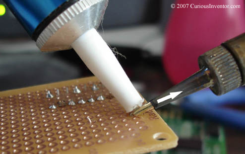
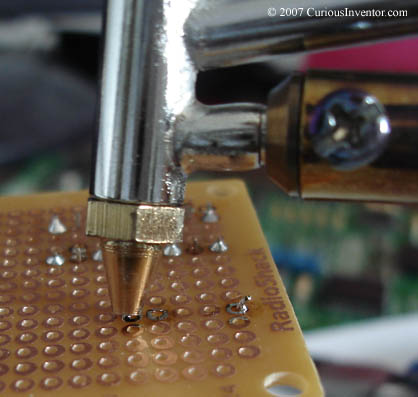
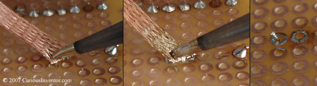
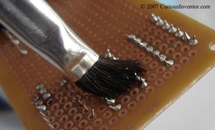
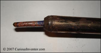
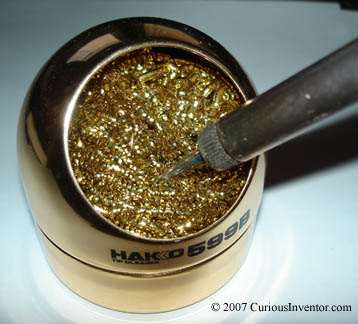
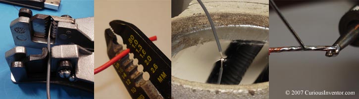
 Wiping the iron on an edge of a hole cut into a sponge can help to remove oxides easier, and also allows waste to fall away. A dry cleaner can also be used. It consists of soft metal shavings that are coated with flux. You clean by thrusting the iron into the shaving a few times. By avoiding the thermal shock of touching a damp sponge, these cleaners help to increase tip life, and in our opinion, do a better, faster job.

Comments:
Feedback and corrections are greatly appreciated.
A very useful page, thankyou.
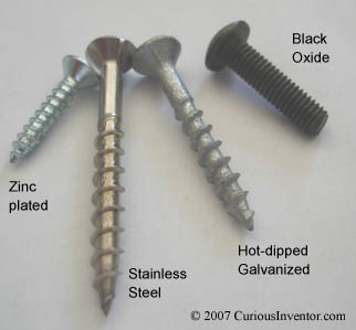
This is a very well written article and I have some information I thought might be helpful. The SAE grade marking for number one is the same as for number two. If you use stainless hardware (bolts, nuts, washers) they will not rust for an extremely long time, even in a salt water environment, unless if they are in contact with carbon steel. Then they will rust. If you have to do any cutting or filing of stainless hardware, clean it with a non ferrous wire wheel or brush after the work is done. There can be enough metal transfer from a file to your stainless piece to cause rust to star. Galvanized hardware is a good alternative to stainless but be aware that the process of making something galvanized requires that it is dipped in a molten metal vat (hot dipping). The coating can increase the size the item in thousandth. Also the galvanized coating on a bolt can make the threads thicker causing binding and seizing of the nut. I have snapped many bolts because of galvanizing. I you need a item to be corrosion resistant and you do not want to buy stainless or galvanized components you can use buy a product called Cold-Galvo or Cold Galvanizing spray. It has many of the same proprieties as hot dipped hardware. Though not as effective as hot dipped, it is easy to apply and dries fast. One note of caution about Cold-Galvo and other such sprays; lots of them contain highly dangerous materials such as lead, be very careful when using them and have the necessary respiratory protection. My thoughts about lock washer; they are fine for use in low to no vibration applications. I have worked on many of an engine and found many high grade lock washers snapped in half. Three things; if you are going to use a lock washer but do not want the material to be damaged put a flat washer between the lock washer and the material being secured. Second, if you want an alternative to the lock washer try using lock tight. It is anaerobic drying glue. It will only dry between the threads of the nut and bolt and it is very strong. Lastly, if you need to have a locking nut and bolt use a lock nut instead. They cost a little bit more but are well worth it. My preference is a nylon lock nut. It has a nylon insert that locks the bolt. The other kind that I know of is a pinched lock nut (I don’t know if that is the right name for it), I have only seen these in aluminum but it looks like a standard nut that is slightly squished, the aircraft industry used them a lot. A note on lock nuts; once a lock nut is used and then loosened, the locking ability is reduced. On last thought about nuts and bolts; it whatever you are doing will need to be undone at some future point and time consider applying an anti-seize compound to the threads of the bolt. Your local auto parts store has tubes of anti-seize but it is of a low grade and works only so-so, but the tubes only costs from $3 to $5. If you can afford it buy an industrial grade. A bottle of industrial grade anti-seize about the size of a bottle of Tylenol can cost you up words of $45, but a little goes a very, very long way. Anti-seize has a melting temperature of 1400 F to 1800 F so it is great for engine work. Most of the anti-seize compounds I have seen are copper or graphite based. I hope my ranting has helped.
Awesome info Mark! That’s interesting about steel shavings enabling rust to start from filing a SS screw.
I’ve heard that an easy way to loosen loctite is to hit the bolt with a flame for a minute. I think they sell high-temp loctite, too, though.
One other “locking nut” I’ve read about is one where the threads are slightly off-pitch, or maybe just the last thread… you end up with definite yielding. If things are tightened correctly, though, this happens a little bit in the last couple threads of a normal nut anyway.