Curious Inventor Blog

Just another WordPress site

HowTo: Make a LoFi Mic from an Old Telephone

he speaker in an old telephone makes a great lo-fi mic. Just wire a 1/4 inch jack straight up to the speaker and enlarge the telephone jack hole to mount it. A small piece of towel helps to muffle some of the air noise. An audio sample and picture of the insides are in the main blog entry. Made by recompas


lofi mic made from a telephone speaker
audio sample
1/4 inch phone jack
We’ve got a couple extra lofi-phone-mics if you want to buy one, just click the contact link and let us know…

Voice of Saturn Updates, Audio

Travis, in recompas, did a set featuring the VOS synth and sequencer, along with a drummer and bunch of other stuff: minimoog and drumset, fender rhodes, roland space echo re201, mig muff pi, univibe clone, ibanez pt909. Here’s some audio. You can keep up with his shows at his blog. He’s also been playing with zoroaster, the loudest band ever, and should be featured on their upcoming album. Lastly, final prototypes of the next VOS module are in pcb manufacturing now. It will be called the ~MODULATOR and have a function generator, voltage controlled amp and a simple attack-release envelope generator.recompas show featuring the voice of saturn synth and sequencer

Enamel coated wire makes neater proto-board connections

If you’ve ever tried connecting more than a few parts with normal jumper-type wires on the bottom of a solder-type proto board (basically a grid of holes), you know how ugly the wiring can get. This instructable shows how to use a home-made needle-in-pen dispensing tool to route enamel coated wire. Making a few wraps on each pin also saves you from using up nearby holes. Will all enamel just melt off when soldered, or would you have to sand off the end? Another question, how well does a normal wire-wrap tool work on regular length leads?

enamel coated wires wrapped and soldered on proto boards with lots of connections

NYC Speed Soldering Contest

Contestants compete to see who can put together a TV-B-Gone kit the fastest… I think the winner is the person who can actually turn off a TV in the room first in case you’re wondering how they know who really is the fastest.

How in the world to giant box staples get installed?

First, it’s gotta be a massive stapler. 2nd, how do you get the “bottom” part of the stapler on the inside of the box? Is it possible to staple both the top and bottom, or do you have to tape at least one?

How To: Make Cheap LaserCut Custom Boxes for Your DIY Electronics

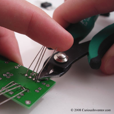
Dremeling out holes for knobs, switches and displays is fun, but several companies now offer cheap laser cutting that lets you make a custom acrylic box with all the right holes and dimensions for under $30. This post talks about how to draw the 6 sides using free software, and how to connect the pieces using screw-together and permanent techniques.

T slots let you screw together custom laser cut acrylic
a square wave pattern makes a strong, welded acrylic joint

Making decent enclosures is troublesome because it’s almost impossible to find just the right size box, and hacking out the holes for connectors usually takes a lot of time and looks sloppy at best. Designing your own laser-cut, acrylic box takes care of these issues and doesn’t even cost that much. Ohararp.com got our pieces to us in 3 days and cost less than $30. Pololu also does cheap cutting.
This will go over our experimentation with a couple different joint styles, some chemically welded with acetone and others held together with screws and nuts. We’ll also talk about drawing the sides with free software and stress test the results.

Joing Two Pieces of Acrylic:

a checker patter makes a strong, welded acrylic joint
Permanent Joints: 
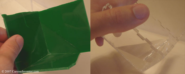
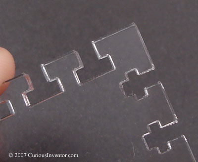
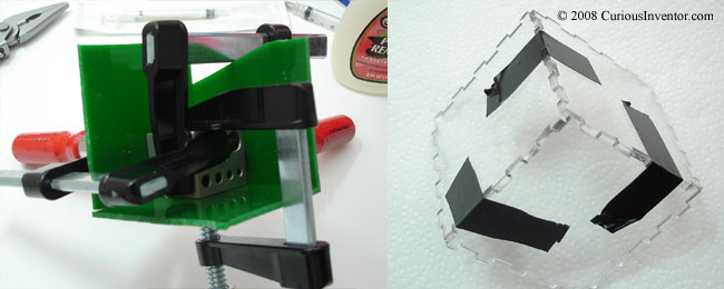
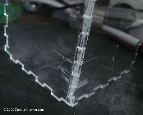
If you want a permanent joint, there are lots of guides already out there that demonstrate using made-for-aquarium glues and / or acetone. We put together two corners using plain acetone: one with flat edges and one with a puzzle-like square wave pattern to see if that added strength. Result: the flat edged (green) corner came apart with a light tug. The puzzle-piece corner (clear) has yet to be destroyed, despite trying to tear it apart at near full-strength. Interestingly, both were water-tight. Instructions for chemically welding with acetone are below.
Acrylic joints welded with plain acetone water tight
Temporary Joints: You typically want to be able to open your box to fix circuitry, replace batteries, etc., so gluing everything together won’t work all the time.
The sturdiest route would probably be to use metal, threaded-inserts that you install by first pre-drilling a hole into the edge, and then “heat staking,” or melting the insert into the plastic (using a soldering iron). You can actually tap (cut screw threads) directly into acrylic, too.
Both of these technique require drilling into the side of the plastic, however, and we wanted something that could be completely cut out of a flat sheet with a laser. We also couldn’t find inserts that would fit in 1/8″ acrylic.

T slots let you screw together custom laser cut acrylic
Another idea, used extensively by the 
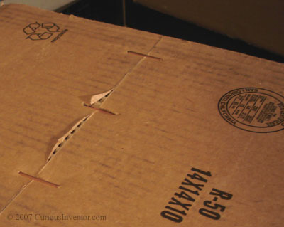
fabathome people, is to use “T”-nuts. A T-shaped gap is made in the edge so that a flat nut can be inserted from the side into the top of the T. Here’s a picof one of the fab at home machines show casing this technique. Unfortunately, we couldn’t find T-nuts small enough, so we decided to try the same idea using just regular nuts. By the way, a lot of these ideas were dreamed up by Daved @ uCHobby.com.

Designing the Joints:

With either the screw-together or glue-together technique, we weren’t sure if the laser would leave a gap for which we’d have to account. As it turns out, at least with ohararp, what little gap there is appears to be under a thousandth of an inch (as measured with calipers). This means that we didn’t have to design in extra material for the width of the laser cut.


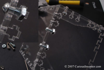
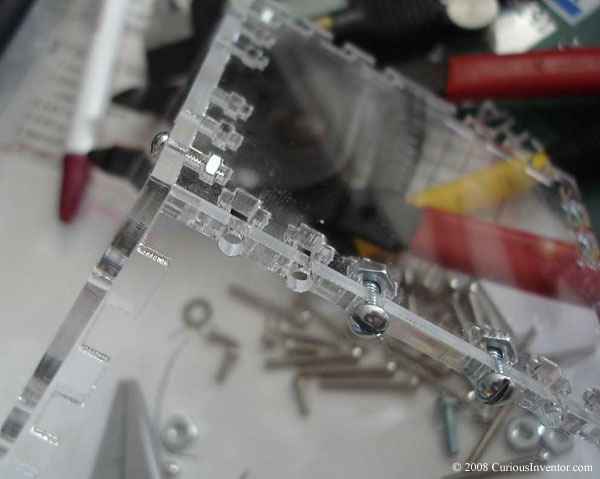
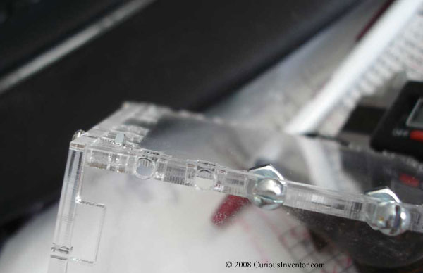
Screw Together Joints:

screw holes cut into acrylic varying distances from the edge
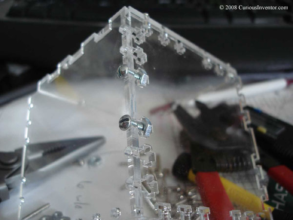
The above two pictures show several different sizes and spacings for the cuts. Although they look the same, each T-cut is slightly different. We wanted to see how “extra space” would affect things. The joint seemed to work just as well regardless of whether the T-cut was exactly the same as the nut or a few thousandths larger.
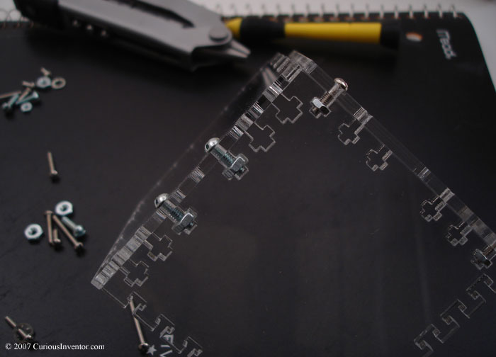
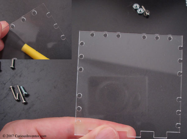
Both 2-56 and 4-40 screws and nuts were used. In all cases, the nuts stick out, but the acrylic sides can be designed to be flush (not overhang) by placing the center of the holes 1/2 the material thickness from the edge. As the picture shows, placing the holes that close to the edge caused the 4-40 screw holes to be interrupted by the outer edge, but the joint seemed to work just as well. Exact dimensions will be shown in the next section.

screwing together acrylic plastic pieces with t-shaped holes for the nuts
 

a lower case t-cut leaves room for the screw to extend past the nut
One useful trick was to make a lower-case t-shape to allow the screw to extend past the nut. This avoids having to use screws that are exactly the right length.

Glue / Chemically Welded Joints

a square-wave pattern on the acrylic's edge makes walls fit together like a puzzle.
We tried both a flat edge version and checkered edge (shown above) to see if the puzzle-piece connection added much strength.
There’s actually software out there that will automatically generate dwg/dxf files given arbitrary box dimensions called Box Maker. This is great if you don’t need to cut your own holes for display and switches, etc.

Drawing the Box Sides with Free Software:

6 pieces with a square-wave pattern fit together to form a box
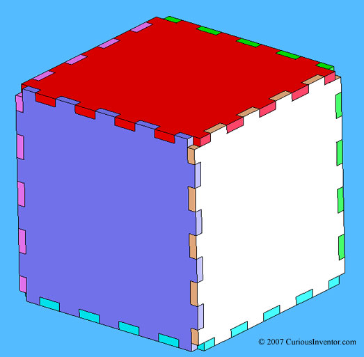
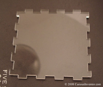
First some pseudo-code for making the square-wave pattern. The above cube is made of 6 copies of the following panel.

6 pieces with a square-wave pattern fit together to form a box
First draw the outline of one face, then sub-divide it into 9 columns and rows, the odd number being important. Then use an offset tool to draw another set of lines inside the outer box by the thickness of the material.

how to draw one 6 of a cube that fits together like a puzzle.
Now get out the trim tool. Two opposite sides should have high portions of the square wave at the edge, and the other two should form the inverse. 4 of the tabs will be a little thinner than the others to allow 3 pieces to fit together at the corners.


Drawing the T-shaped holes

Dimensions for 4-40 and 2-56 T-nut slots.
The dimensions on the t-shaped holes were barely big enough for the nuts, but we found the joints still worked well with a little extra slop. Not all nuts are created equal, you might want to add in a couple thousandths margin.
If you don’t want any overhang, draw the clearance holes for the screws at half the thickness of the material. This will cause a 4-40 hole to go past the edge on .118″ thick material, but this didn’t seem to hurt the joint much. Compression holds the pieces together, not the side wall of the screw hole.

Free CAD Software:

Talk to your laser cutter to see what format they will accept. Typically, any sort of vector-based file will work, such as dxf or eps will work.

  • Alibre: From our very brief testing, this appears to be one of the best free offerings out there. 2D and 3D, similar feel to SolidWorks if you’re used to that.
  • freebyte.com/cad: A good listing of free / open source software.
  • Cademia: open source and cross platform
  • QCad: Only free for linux.
  • SolidEdge: 2D only, fairly easy to use interface.
  • A9Tech: The simplest to use out of the box, you can save as dxf, but not pdf, jpg, etc.
  • CADStd: Another fairly easy-to-use windows program that exports dxf.
  • Many drawing programs will also work, and if you already have a CAD program (like Eagle) for electric circuits, check to see if it will export dxf.

Be prepared to fight a learning curve if you’ve never used a CAD program before; they’re a little trickier than photoshop. Some tools to get familiar with include O-snaps, linear patterns and offsets.

Welding the Acrylic Sides Together with Acetone

Tools for joining acrylic: acetone and a syringe
Lots of guides recommend using a special aquarium glue to join pieces together, but we had success just using straight acetone from the hardware store. This may only work well when the gaps are very small and capillary action can pull the acetone between them.

Dissolving acrylic in acetone
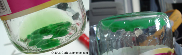
If there are rougher edges, some recommend making a mixture of acetone and acrylic by dissolving some acrylic pieces in a jar of acetone over night. The thicker mix may better fill gaps. After a few hours, the acrylic starts to soften (left), and after a day, a thick syrup is all that remains.
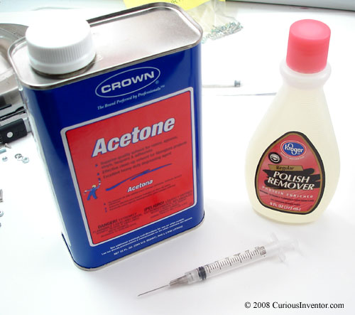
The syringe is very helpful for applying the acetone only to the joint. Any spills will immediately start eating into the plastic and damaging the surface. I got a free one from a local Kroger pharmacy. I think the pharmacist actually believed me when I said it was for a hobby project.
About Acetone: Acetone is an interesting chemical, commonly used to thin epoxies, remove paint, clean greased parts (bicycles), it is also the main ingredient in nail polish remover. (We tried using nail polish remover to join parts, it did not work…) deoxy.org says even the vapors can damage cds. It evaporates quickly, is highly flammable, and is heavier that air, so it’s probably not a good idea to use near a pilot light. The fumes attack the central nervous system (see msds), can harm the lungs, and eventually cause unconsciousness. The liquid will damage skin. It also makes great acrylic joints!
According to wiki/Plastic Welding, in solvent welding, acetone dissolves the plastic which allows the sides to “mix”. Then it eventually permeates out leaving behind a solid acrylic connection.


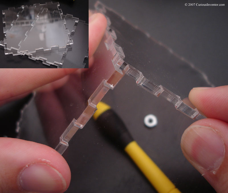
Clamp or Tape the Pieces Together:

Clamp or tape the acrylic before applying acetone
First, figure out a way to clamp or tape the pieces together. The green pieces have straight edges and the clear ones have square-wave shaped edges that fit together like a puzzle. Clamping the pieces (green) to a block turned out to be a bad idea because the acetone was pulled underneath it.

applying acetone to acrylic using a syringe
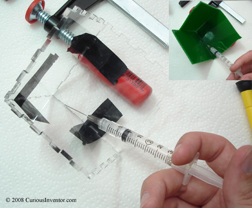
Now apply a small amount of acetone with the syringe along the inside seam. Capillary action should pull it into the joint. We repeated this a few times to make sure all the gaps were filled, letting it sit a few minutes between each application.
Let it sit for 24 hours. It might be fine after 2 or 4 hours, test for yourself!

two small acrylic pieces welded with acetone
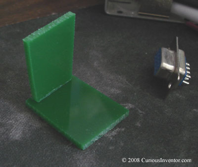
To get a better idea on the strength of a straight edge joint, we made a small 1″ joint, also. Surprisingly, it survived over 3 lbs of tensile force before breaking!

acrylic pieces joined with acetone under magnification
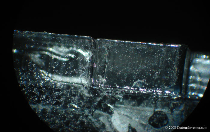
Wonder whether the gaps actually got filled? Here’s a picture under 20X magnification after everything has hardened. Almost every single gap was completely filled.

Conclusions:

Acetone Welded Pieces: As we mentioned at the beginning, the square-wave puzzle-shaped edge was amazingly strong, whereas the flat edges broke easily. This could have been due to some unevenness in the flat edge, since the small 1″ test piece survived over 3 lbs of force over a very small area. One thing to watch out for is the acetone being wicked away from the joint by whatever is clamping the pieces together. You can see some marks where it got under the tape in the final picture below.
T-Slot Screw-Together Method: These joints seemed surprisingly strong. Some lock washers would probably help prevent loosening from vibration. One downside is that the nuts stick out from the side a bit, but there might be some smaller t-nuts out there that will fit inside a 1/8″ or 3/16″ piece of acrylic. Another method might involve making tabs on one piece of acrylic that fit into slots on another, with everything being held together with long screws and standoffs. Leave better ideas and corrections in the comments… this isn’t a tried-and-true method yet!

custom box made from acrylic pieces with square wave edges welded with acetone screwing together acrylic plastic pieces with t-shaped holes for the nuts
screwing together acrylic plastic pieces with t-shaped holes for the nuts screwing together acrylic plastic pieces with t-shaped holes for the nuts

Ball Balancing Table Can Catch

dsPIC + touch screen + 2 servos. Perhaps even more interesting is how Evidence generated the code for this demo app. An open-source matlab / simulink called SciLab lets you graphically model the control system and then automatically generate C code (with Evidence’s toolbar). Unfortunately, the generated code only works on their real-time embedded OS ($$$$). No free lunch.

Keep Clipped Leads from Flying

This is a small but useful tip we got from talking to David at uCHobby about lead trimming. When leads are clipped they usually go flying off and are a pain to clean up as well as an eye hazard. By resting a finger on the tip of the lead while clipping, the lead just falls to the table. It’s faster than grabbing the sides of the lead, although with thicker leads (voltage regulators, some diodes, etc.), grabbing the sides is more prudent unless you don’t mind a lead hanging out of your finger.


Intro to Logic Analyzers

A logic analyzer isn’t the most common piece of equipment in a hobbyist’s shop, so we thought we’d write a small introduction about what it is and what it’s good for. A logic analyzer is commonly used to debug circuits where two or more chips are talking to each other, like a central uC interfacing with external memory, a peripheral camera or mp3 decoder. The main advantages over an oscilloscope are that more than 4 channels can be watched at the same time (sometimes more than 80), and that the logic analyzer can trigger / record right where it’s needed, not just on the first (or every) rising edge. For instance, you could program one to trigger and record data only after a particular byte sequence occurs. Read on for the (brief) basics of how to use a logic analyzer, what features to look for, some links to inexpensive analyzers as well as home-brew versions, and our attempt to digest a play station 2’s controller protocol.


small disclaimer: This is for a beginner and written by one… please point out errors and omissions!

Features and Basics of operation:

First, a small sanity saving feature: labels.
Instead of input 1, 2, 3,… the inputs can be labeled CLOCK, WRITE_ENABLE, CHIP_SELECT, etc., and multi-line buses can be configured to display hex values instead of binary. Reading a sequence of hex values (0x4D etc) is much easier than trying to decode stacks of square waves byte by byte.

State Analyzer or Timing Analyzer mode:

There are two modes that determine when a logic analyzer will sample:
In State Analyzer mode, the logic analyzer samples all the test signals on the SUT’s (System Under Test) own clock signal, so the analyzer sees data exactly the same as the test circuit.
In Timing Analyzer mode, the logic analyzer uses its own internal clock to decide when to sample. This mode provides more resolution, and is useful for making sure all the signals in the test circuit are transitioning correctly, ie, data is stable a sufficient amount of time before and after the clock signal. High end analyzers enable overlaying of both state and timing information to speed troubleshooting.

Triggering:

Besides having many more channels available than an oscilloscope, the other main advantage of a logic analyzer is its ability to record only the data of interest, even if it’s buried in the middle of a complex and long exchange. For example, a trigger could be designed to start recording only after seeing a particular bit pattern 4 times, followed by a delay, followed by another particular pattern, etc.
Newer PC-based logic analyzers make use of the PC’s infinite storage, so precise triggering isn’t necessary to capture the target communications. However, many argue that it’s better to setup a precisely targeted trigger in the first place to avoid spending time searching through megabytes of data. ECNasia mag has a good review of many inexpensive PC-based analyzers, some of which are even less than $200.
This hack-a-day comment listing includes lots of great links to parallel port and other home-brew logic analyzers.

Programming the Trigger:

example trigger programming sequence levels
Trigger programming used to detect a configuration command from a play station 2
Doug Beck of HP has an excellent introduction to trigger programming and some common mistakes. The basic idea is to set conditions for when the analyzer should record. The conditions typically involve a sequence of events and not simply a rising edge. For instance:

  1. 1) wait until DATABUS = 0x3D
  2. then, if WRITE has 4 rising edges within 400 ms, goto 3, else goto 1
  3. 3) Record whenever ADDR = 0x56 (until record buffer full)

Each clock cycle of input data is tested against a step’s conditions until they are met, at which point the analyzer begins comparing input data to a new step in the chain. Note: after a level is completed, new input data is collected to test the next level. So if you wanted to check to see if ADDR=0x3D at the same time as DATA=0x32, both of these tests would have to be performed in the same level using an AND operator, not two different levels. The basic building blocks include timers, counters, Boolean logic , comparisons and edge triggers.
One very useful feature is the ability to automatically digest serial data (USART, SPI, I2C, etc.). This feature isn’t included in all logic analyzers, so be sure to look for it when purchasing.
This excellent Tektronix XYZ’s of Logic Analyzers ( / Advertisement for their $10k+ analyzers) says channel count is still important even for serial-only applications, because 32 bit instructions get re-mapped vertically across 32 different channels even though the data stream comes in on one wire.

Finding the Configuration bytes in a PlayStation 2’s Initial Hand Shaking with a Controller:

logic analyzer probing play station 2 cable
In our efforts to develop the MIDIATOR kit (PlayStation / Guitar Hero –> MIDI), we spliced into an extension cord and attached oscilloscope and logic analyzer probes to the Command, Data, Clock and Attention Lines. Also shown in the picture are some PICs that were used to listen in on the serial (SPI) communications and dump out the data to a computer via RS-232. The MPLAB C-code is available on our PS2 Interface Guide.
In this case, we got away with sloppy wiring since the PlayStation protocol is relatively slow (500kb/s), but attaching probes can require careful consideration of how much the probes themselves will affect a circuit. Too much added capacitance will cause the rise and fall times of a fast signal to round, which could lead to erroneous readings. Many modern circuits are designed with special interfaces just for logic analyzer probes. This is especially helpful when there are upwards of 64 lines to watch.

logic analyzer and oscilloscope displaying and comparing the same signals
The logic analyzer does not record unnecessary analog data, and has a much larger memory that you can zoom in on and scroll through.
Unfortunately, this particular analyzer did not have built in functionality for analyzing and triggering off serial data (only parallel), but we were still able to setup a trigger that found the configuration byte, and then recorded after a certain delay. The trigger uses edge detection and a timer to find a step of a certain size. Admittedly, a better example would have involved a parallel bus, but we were still able to get more out of the communication than with an oscilloscope.

About

CuriousInventor launched in late 2006 (pre-arduino era!) as a place to enable hobbyists, students, and musicians to create their own technology. We sold open-source kits and tools, and offered numerous guides & videos on things like soldering, metal working, screws, electronics, and more. 

The store is now mostly empty, but we’ve kept the product pages and guides up since they have useful information. Many of our guides and videos still rank on the first page of google searches and have been seen millions of times. Content on this site and the CuriousInventor YouTube channel produced by Scott Driscoll.

Top Videos