(and other small packages like capacitors, MELFs, DPAKs, SOTs, etc)
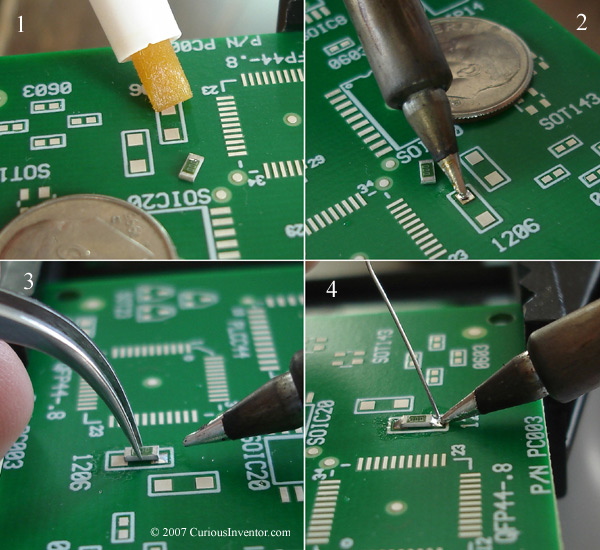
The basic steps for soldering most of these components are: add flux to the board, tack one pin of the component and then solder the other side. The picture below outlines these steps; more details follow below.
The basic steps for soldering surface mount chips (a 1206 resistor is shown): flux the board, tack the component and then solder the other side.
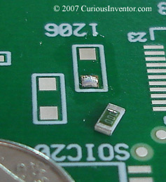
A quick word about the packages: The resistive element is the colored side of a resistor, so it should face up to help dissipate heat. 1206 refers to the dimensions of its shape: 120 thousandths of an inch by 60 thousandths. 603’s are 60×30 thousandths and so on.
-
- add flux to the board: For larger components, like this 1206 resistor, you might not need flux if you melt flux cored solder directly on the pad. For smaller chips, however, oftentimes tinning the pad with wire solder will result in too much solder–a light touch with a tinned tip is all that’s required. In this case, extra flux is needed because no active flux would be left in the solder that’s on the tinned tip. Flux becomes active and quickly gets used up on the hot iron tip.
- add a small amount of solder to one pad: Again, very little solder is needed. Touching the pad with a tinned tip will provide all that’s needed for 603 and 402 sized chips. If you’re attaching a DPAK or SOT (small outline transistor), tin the largest pad (usually the heat sink) first. Tacking a smaller pin first will work, too, but you’re more likely to reheat all the pins when you heat up the larger heat sink later.
The first pad with solder added.
- tack one side:Using tweezers, lightly press down on the resistor and touch the junction between the chip and pad with a clean iron tip. You should feel the resistor drop into place. Ideally it would lay completely flat, but this isn’t an absolute requirement.
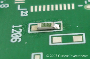 One side of a 1206 resistor tacked
 - add solder to the other side:Rotate the board and add a small amount of solder to the other side. To do this, hold the tip so that it touches both the component and pad, and then lightly touch it with solder. I like to add more flux to the 2nd side sometimes before this, but if you’re going to melt solder directly from the wire, it’s not necessary. For smaller packages, add a small drop of solder on the end of a clean iron tip first, and then touch the tip to the component and pad. This will help avoid adding to much solder.
Adding a small drop of solder to the end of a clean tip

- touch up the first side: If necessary, add more solder to the first side.
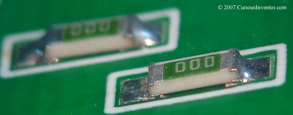
- finished result:The most important thing is that the solder looks like it adhered or clung to the metal. There should be a smooth fillet or ramp connecting the pad and resistor. A large blob of solder may work, but it’s hard to tell whether the blob is just sitting on the joint, or has actually bonded with the metal. The shininess of the joint is less critical. Lead-free solder won’t be shiny at all, and some types of flux in lead-bearing solder will result in duller joints that are still perfectly fine.
An ideal 1206 solder joint
These same steps can be used to solder just about any package with only a few pins.