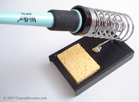
CuriousInventor.com Logo

VMeter: USB Touch Strip Volume Control

 Out of Stock? We've received a lot of emails asking about out of stock items, and sad to say, but CI is downsizing to a much smaller product offering. All of our guides, schematics and blog entries will stay available forever. Our new project is VMeter--a USB MIDI Controller Touch Strip & Display.

We talk about solder paste, cheap kapton stencils, how to make a home-made vacuum pick-up tool, and toaster oven reflow temperature profiles. Read More
0 Comments | Posted in Soldering By Scott Driscoll

Drag Soldering HowTo Demo

July 4, 2010 3:40:00 PM EDT

 Here's a quick video of drag soldering--a technique that enables you to quickly solder entire sides of ICs by simply dragging the iron across all the pins.  The key is starting with the right amount of solder, and adding generous flux.  The results are often better and more uniform than individual pin soldering. 

Read More
1 Comments | Posted in Soldering How-To & Quick Tips By Scott Driscoll

A common mistake we've seen in our classes--as well as from experienced 'solderers'--is to clean the tip before putting the iron back in its stand.  This habit leaves the tip exposed to oxygen in the air which works quickly to oxidize (basically rusting) the end of the tip.  Almost all metals oxidize in air, and they do so much faster at higher temperatures.  When your tip is thoroughly oxidized, it will look burnt, and no solder will stick to it. And if solder won't stick to it, you won't be able to create a "heat bridge" of solder between the iron and part, and very little heat will transfer.

To avoid this, coat the tip with a large blob of solder every time before returning it to its stand.  While flux in the solder gradually eats away at the tip, oxidation will cause problems much faster. 

You may notice that new tips actually come coated with solder. We've seen manufacturer documentation recommending that you hold solder against a new tip the first time you heat it up so that the tip gets coated as soon as it's hot enough to melt solder.

Cleaning tip: If your tip is starting to look brown, and won't 'hold' solder, or the solder acts like water on a freshly waxed car, you can help restore it by repeatedly applying solder and wiping it off.  The flux in the solder acts like a cleaning against against the built up oxides.  It may take 20 or more cycles of this to get the tip back into shape.

Read More
5 Comments | Posted in Soldering How-To & Quick Tips By Scott Driscoll

This video demonstrates how to solder a QFN or MLF chip without solder paste or stencils.  While solder paste and a stencil will product the most consistent results, this demonstration only uses an iron, flux, hot air and regular solder to get the job done.  

Future videos will demonstrate how to use a solder paste syringe, as well as the recommended method of using a stencil.

Equipment used in this video:

Read More
0 Comments | Posted in Soldering How-To & Quick Tips By Scott Driscoll

An Extra Set of Hands You Never Knew Existed

February 10, 2010 4:11:00 PM EST

For everyday tasks like tinning wires, it is difficult to hold the iron, solder, and wire in only two hands. To remedy this problem, you can jam the soldering iron in the coil of the iron holder.
Read More
1 Comments | Posted in Soldering By Oren levy
Resistor Why is it easy to find 4.7k resistors, but not 4.8k resistors? Where do common values like 1.2k, 2.7k, 560, and 820 come from and who decides them? As you may know, resistors come in different tolerances, as indicated by the 4th band (gold = 5%, silver = 10%). A 100 ohm resistor with a 10% tolerance is expected to have a value somewhere between 90 and 110 ohms, so it wouldn't make much sense to buy a 101 Ohm resistor when it's actual value could be less than a 95 Ohm, 10% resistor. The Electronic Industries Association (EIA) is the primary body that standardizes the values for resistors, and they publish value lists called "E" series. In the 10% series, known as E12, each value is spaced so that there won't be overlap. The min and max values are listed:
(min) value (max)
(90)100(110)
(108)120(132)
(135)150(165)
(162)180(198)
(198)220(242)
(243)270(297)
The number following the "E" stands for the number of logarithmic steps per decade. Logwell has a table that lists common values from 10% through 1% Here is a neat resistor selection tool from uCHobby that allows you to select only legal values Read More
2 Comments | Posted in Soldering By Abhishek
A SMT soldering class was taught at Atlanta's new hackerspace: freeside. It focused on using stencils (from ohararp) and solder paste on a skillet and in a toaster oven. The video shows the amazing ability of the solder's surface tension to pull chips into alignment once the solder liquifies. Read More
0 Comments | Posted in Soldering By Scott
After ordering a new pcb and populating all the components, sometimes you'll find a short between two signals. This can be especially hard to track down if it's touching a gound or power signal that travels all over the board. Worse yet, sometimes the short is on an internal layer and can't be seen.

Common Causes:

  • A small solder bridge or ball between pins: Sometimes small strands of solder will bridge two pins--this is especially easy to do on "bard bones" boards without any solder mask. Using too much solder paste, or paste that's past it's prime, can also lead to bridges or small balls getting lodged behind pins. The balls are especially hard to remove since solder wick usually can't reach them. Sometimes a thorough flooding of solder followed by more wicking will work.
  • Incorrect components / pinouts: Make sure the pinout on that spare voltage regulator you had lying around actually matches the layout connections.
  • PCB manufacturing erros: Sometimes you'll find hair-line connections where they shouldn't be, especially in areas close to the manufacturer's limits.
David at uCHobby.com had some good tips for finding shorts in printed circuit boards.
  • The obvious thing to try is to start removing components and isolate sections of the board. This may also require cutting a few traces.
  • If you've already taken all the components off, and carefully checked over the board for obvious errors, try running a few amps through the offending traces. If it's a hairline pcb manufacturing mistake, the small thread of conductor will burn up under the amperage. Your other traces, even ones as small as 8mils, should be fine for a short time under a few amps.
  • Lastly, if you've narrowed down the short but can't see it because it's inside the board, it might be time to drill. David had some horror stories about drilling through 10 layer boards to fix one trace while breaking traces in 7 other layers. Have some "green" or "white" wire handy to jumper the broken traces.
  • Any other ideas for quickly locating a short without resorting to board surgery or removing all your painstakingly placed parts?
Read More
2 Comments | Posted in Soldering By Scott

Mercury Tilt Switch - Old School Accelerometer

June 8, 2009 10:26:00 AM EDT

Rummaging through the ubiquitous box of random stuff, I pulled out a mercury tilt switch, which were / are used in vending machines, thermostats, and construction equipment to detect tilt. The liquid drop of mercury conducts current when it bridges two contacts at one end, and, according to wikipedia, can operate millions of cycles since there's no wear. Anyone know the right way to dispose of these? Read More
0 Comments | Posted in Soldering By Scott

poor man's clamp

September 4, 2007 3:12:00 AM EDT

When soldering a lot of surface mount chips, or when you don't have a clamp handy, sometimes the best solution is just a piece or two of double-sided tape between the board and desk. "De-stick" the tape a little by touching it with your fingers to avoid permanent additions to your desk and to make it easier to rotate the board when needed. Only a small amount of tape is needed.
Read More

Tags:

0 Comments | Posted in Soldering How-To & Quick Tips By Scott