The father and son (only 11!) duo behind arduinofun.com put together a tutorial / instructable for building the roboduino kit–a arduino-compatible that’s servo/battery pack friendly. Thanks guys!
Beatrix*JAR Circuit Bending Workshop & Concert @ Eyedrum, Atlanta
Beatrix*JAR puts on a show at the Eyedrum in Atlanta and does a circuit bending workshop following the show where they explain how they make and use Speak n spells, AM radios, flash cameras and old casio keyboards. One very cool effect involved an AM radio and two flash cameras, which can be used as a makeshift theremin by charging the cameras and moving them around the AM radio. When the flash is triggered it lets off an explosion of sound on the radio. In the circuit bending workshop, they show how to warp an old casio’s sounds by randomly bridging points on the insides. This was surprisingly effective and no magic smoke was seen. They also embedded nails into some speak-n-spells that would warp the pitch depending on how hard the nails were pressed.Beatrix*JAR Circuit Bending Workshop & Concert @ Eyedrum, Atlanta from CuriousInventor onVimeo. 


PCB as a Heat Sink + Calculating Trace Width for Given Current
This entry will take a dive into heat and temperature issues surrounding circuit layout design, including the effectiveness of the PCB itself as a heat sink when a voltage regulator’s heat sink is soldered directly to the board, and how to size trace widths for given current loads.

This article was written while writing a spec for the Roboduino Kit. One of the first questions is “How many amps can it deliver?â€
Our DPAK 5V regulator (https://www.st.com/stonline/books/pdf/docs/9614.pdf) is rated at 1.5A, but this amperage would likely require some serious heat sinking.
As a review, the total heat generated by the regulator is just the energy in minus the energy out. This is how linear regulators work—they turn excess energy straight into heat.
heat generated = (Vin-Vout)*I
(there’s also quiescent current in there which is the current used by the regulation circuity, but this is around 50mA, so we’ll ignore it for brevity).
So, if Vin = 9V, Vout = 5V, and I = 1amp, the heat generated would be about 4W.
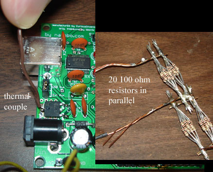
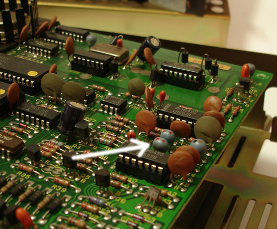
As it turns out, our board was only able to dissipate about 2W. A bundle of 20 1/4W resistors (100ohms, 10ohms total) was used as a dummy 1Amp load at 5V. A thermal couple measured regulator temperature at the solder joint. Current was measured before it entered the Roboduino’s input.
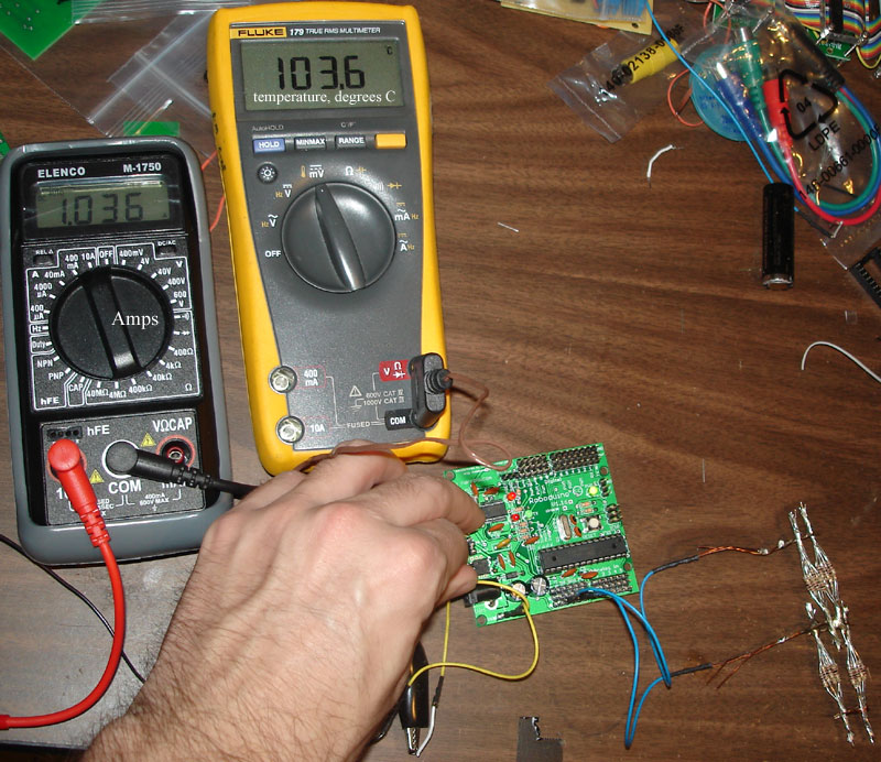
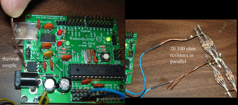 [setup pictures]
So, while the voltage regulator can handle up to 1.5Amps and 25-30 Volts on the input, any high amperage or large Vin would require some additional heat sinking, forced air or an extremely cold environment. The ambient temperature (Tamb) was about 24 deg C in these tests.
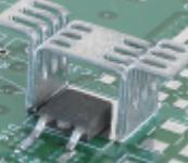
(There are, by the way, DPAK and other surface mount chip heat sinks that saddle over chips: www.aavidthermalloy.com/products/standard/surfacemount.pdf )
When Vin was 8 volts or higher, the regulator temperature rose to 125 deg C after a few minutes and its internal thermal protection circuitry shut the regulator down.
How Much Heat Can the PCB Dissipate from surface mount components (SMT)?
Robert Kollman of TI has a great article on Power Supply Layout Considerations (https://focus.ti.com/lit/ml/slup230/slup230.pdf) that covers heat transfer through the board and its traces, (as well as lots of useful info on parasitic inductances / capacitances, ground design, and voltage losses through traces).
We’ll summarize the highlights and conclusions, but first some basic structure on how these types of heat transfer problems are thought about and solved:
In most cases, there is a temperature that will break something: either the pcb board material (FR4) will break down or a device will become permanently damaged or shut down. In the case of our voltage regulator, it shuts down at 125 degrees C.
The next question to ask is “What will the ambient temperature be in which the device operates?†The best heatsink in the world won’t help if it needs to operate in the desert and components fail at desert temperatures (or automotive: -40 to 125 deg C).
The final operating temperature will be:
T_device = T_ambient + Q*R, where Q is the heat generated and R is the total thermal resistance between the device and the outside air.
Rearranged, (Td-Tamb)/R = Q, which is analogous to V/R = I, where voltage is T and current is heat.
So, in the design stage, you’ll need to make a best guess at what the ambient temperature will be, and then you can calculate a target thermal resistance. Typically “trace width calculators†and other guidelines are written in terms of an “acceptable temperature rise,†(Td-Tamb).
In the case of a CPU with a heatsink, you would add up the resistance of the “junction to case†(resistance from the actual heat generator to the outside of the package) + the heatsink interface resistance (thermal paste, negligible for soldered joints) + the resistance of the heat sink to the surrounding air. The device’s manufacturers would provide all of these numbers.
However, when a component is soldered directly to a board, there are no easily-looked-up numbers past the “junction-to-case resistance.†You’ll have to estimate how much resistance there is to heat traveling through the board (conduction) and also into the air (convection).
To get a frame a reference, the convection thermal resistance of still air is about 166 C/W sq in, or in words, 1 Watt going through a square inch will cause an increase of 166 deg C in temperature. (that number may be a little conservatively high). So, say you wanted to keep your temperature rise at 80 deg. C (would put our device a little over boiling), @ 2W, you would need ~4 square inches. But you also have to take into account the resistance the heat encounters while spreading out.
An interesting note from Kollman is that heat travels 30 times more easily through 1oz (1oz / sq. foot, 1.4mils thick) copper than .06†FR4, 60 times when 2oz copper is used. So the best way to spread heat out is to employ large copper planes.
What about planes on both sides of the boards? Despite the high resistance of the FR4 material, the large surface area moves heat somewhat easily between top and bottom planes, more than 20 times easier than the heat transfers to the air via convection (p. 4-14). So planes on both sides will help immensely. A handful of vias can help distribute heat, too. Twelve 17mil sample vias equate to the same resistance as 1 sq. inch of bottom-to-top plane resistance (8 deg C/ W in the paper).
One other factoid about heat spreading through planes is that gaps significantly block transfer, so continuous planes are most helpful.
Kollman simulates a small 5mm circular 2W heat source on a board with copper on the top and bottom (2oz). Most of the heat was dissipated within the first inch around the device. The final simulated resistance was around 15 deg C/W, but Kollman says practical experience places this value closer to 20 or 30 deg C/W.
In our testing of the Roboduino, which has copper fills on both sides of the board, many vias connecting the planes at the regulator, but also lots of traces cutting up the planes, we got measured about 38 deg C/W with the following conditions:
Tamb = 24 deg C Tdevice ~= 100 deg C Q (heat) = 2W Total resistance = (100 – 24 ) / 2 W = 38 deg C/W.
We estimate that a similar thermal resistance would be found on the Arduino Diecimila and Freeduino, after which the Roboduino was closely modeled.
One final note is that some heat will also leave via radiation. Kollman estimates radiation to be about half as effective as convection (in a “black body†room), but he says that most engineers use this as a margin of safety rather than incorporating those calculations.
Trace Width Calculations: How Wide for a Given Current?
The Roboduino board also supplies power straight from the voltage input to various pins so that servos can be driven at Vin, not 5V. We needed to design the traces powering those pins so that they could carry sufficient current (4-5 amps).
https://circuitcalculator.com/wordpress/2006/01/31/pcb-trace-width-calculator/ is a useful calculator for calculating necessary trace widths (and also great Q&A’s in the comments). You will, however, need to decide what an acceptable temperature rise is before using the calculator.
Previously, our voltage regulator would shut down at 125 deg. C, but in the case of a trace, the limiting factor is damage to the pcb material itself. Judging from comments posted around the internet, it seems that most people use a 10 deg “acceptable temperature rise†when they want to question of whether the device will work or not. Some others from industry claimed to have used 30 deg C for products.
If you are fairly sure your device will not operate in an ambient temperature greater than 50 deg C, (122 deg F), 30 deg. seems excessively conservative.
Our board is FR4, which has a Tg (glass transition temperature) typically between 115 and 125 deg. C (this depends on the exact materials used by the manufacturer). What is the glass transition temperature? According to https://www.arlon-med.com/Everything%20You%20Wanted.pdf , it’s roughly when the material changes from a hardened state to… something less hard, maybe rubbery. The article points out two consequences of reaching that temperature:
The bond strength between the resin, laminate and copper foil becomes weaker, so pads and traces are more likely to lift. Also, the coefficient of thermal expansion (how much larger things get for each degree increase in temperature) goes up dramatically, which can cause plated through holes and via barrels to crack. Finally, prolonged exposure to higher temperatures can oxidize the hidden side of traces, which further weakens their connection. Chet Guiles (author of above link) seems to indicate that operating “close†to the Tg is a bad idea. There is also the RTI (relative thermal index), which is published by the UL. This number is supposed to be the point where the device will operate for 100,000 hours and still retain 50% of its original properties. It’s unclear how to go from either of these numbers (Tg or RTI) to a “safe†acceptable temperature rise.
Italian Guides for Voice of Saturn Modules
noisecollective.net has written a set of tutorials for out Voice of Saturn line of kits in Italian. They also have tutorials on max, cubase, monome and other suitably noisy machines. Thanks! L’ultimo prodotto a catalogo (per il momento) è il VoS ~Modulator, una unitàche accoppiata al Voice of Saturn (ma a qualsiasi fonte sonora) daràgrandi soddisfazioni agli smanettoni che ogni tanto fanno capolino qui su Noisecollective. 
Scrubbing Sampler with Stribe1s and monome
The demo uses the monome to trigger different play positions in loops and Stribe1s to adjust playback speed, pitch, and to scrub / scratch through the samples. The software is written in max/msp and is based on granular synthesis, which breaks the sound into small chunks that get overlayed and blended together. The code (dirty beta) will be linked at the end of the post. Stribe1 Monome Sampler Scrubber from CuriousInventor on Vimeo. Code: max/msp code. (warning, VERY ugly and will take some pecking to get operational. post questions in the forums, not in the comments here). Thanks to Andrew T. for the Stribe1 / monome arrangement idea.
How the Yellow Line is Drawn in Football Coverage
As you might expect, the camera position, angle, zoom etc are fed back to computers where the green field is replaced with yellow. Interestingly, one operator’s entire job is to match the replacement color to prevent the line from drawing on top of players when it’s muddy or foggy. Are green pants illegal now?
Name That Component: Taking apart a 1983 Floppy Drive
Taking apart a floppy drive from 1983 that was longer than most computer cases, we found some interesting components you don’t see much today. Like an old car, things are a lot more spread out and bigger, so it’s easier to see how things work. Click the title for more pics.

What is it? Let’s crack it open!

Inductor! (check out the small coil) (anyone know the specific type?)

Check out the cursive Toshiba font.

The entire drive is over 14 inches long. But it does have it’s own transformer and power supply circuitry.

Two stepper motors spin the disk and slide the reading head.
Thanks to Oren for pointing out some of the neat stuff.
Nixie Tube Gmail Unread Mail Count / Notifier
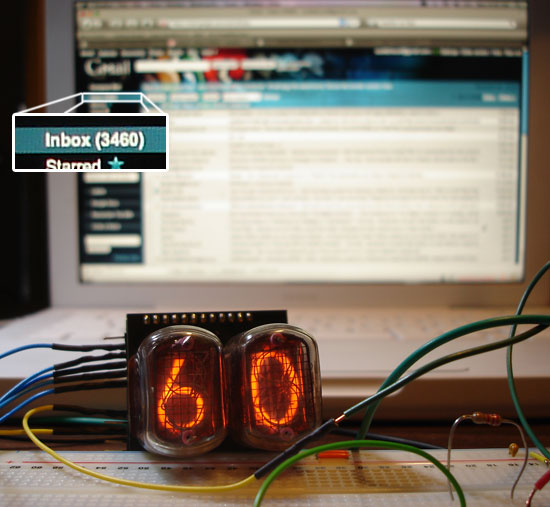
Inspired by the glowing cube gmail notifier, and having been given a nixie duo + driver from ogi lumen, this entry demos how to make a nixie display that shows the last two digits of your gmail unread count. It uses a python script to check your gmail atom feed, a $7 disposable camera circuit to power the tubes at 170VDC, and a roboduino (or any arduino compatible) board to control the nixies from the computer via USB serial. Click the title for more details.
Getting the Gmail unread count: This turns out to be surprisingly easy with universal feed parser, one line in fact. After getting the count, mod it by 100 to get the last two digits, and then send it out the serial port to your arduino once a second. This is mostly what J. Matthews did, except this script runs periodically in a python loop instead of using the OS X launched services. It would be easy to get local weather or just about anything else using urlopen, also.
Python Code:
import sys, feedparser, serial, time

#Settings - Change these to match your account details

USERNAME="youremail@gmail.com"

PASSWORD="yourpassword"

PROTO="https://"

SERVER="mail.google.com"

PATH="/gmail/feed/atom"

SERIALPORT = "/dev/tty.usbserial-A900acn6" # Change this to your serial port!

# type ls /dev/tty.usbserial* to find out what your USB serial port is

# Set up serial port

try:

ser = serial.Serial(SERIALPORT, 9600)

except serial.SerialException:

sys.exit()

time.sleep(1.0)

while (1):

newmails = int(feedparser.parse(PROTO + USERNAME + ":" + PASSWORD + "@" + SERVER + PATH)["feed"]["fullcount"])

print(newmails)

# get last two digits

newmails = newmails % 100

print(newmails)

ser.write(str(newmails))

time.sleep(1.0)

time.sleep(1.0);

# Close serial port

ser.close()
Arduino Code:
/*
nixie_example.cpp – sample code using the Nixie library
for controlling the OGI LUMEN NIXIE DRIVER KITs.
Created by Lionel Haims, July 25, 2008.
Released into the public domain.
*/
#include
#include <Nixie.h>
// note the number of digits (nixie tubes) you have (buy more, you need more)
#define numDigits 2
// note the digital pins of the arduino that are connected to the nixie driver
#define dataPin 2 // data line or SER
#define clockPin 3 // clock pin or SCK
#define latchPin 4 // latch pin or RCK
// Create the Nixie object
// pass in the pin numbers in the correct order
Nixie nixie(dataPin, clockPin, latchPin);
void setup()
{
// Clear the display if you wish
nixie.clear(numDigits);
Serial.begin(9600);
}
void loop()
{
// just some local variables to help the example
static int i = 0;
int ser_in;
int ser_num;
static int digits<2>;
// this is a little ugly–didn’t know how to send a single byte out of python,
// so here we interpret 2 digits.
if (ser_num = Serial.available()) {
if (ser_num == 2) {
digits[0]> = Serial.read() -48; // get first digit
}
else if (ser_num == 1) {
digits[1] = Serial.read() – 48;
ser_in = digits[0]*10 + digits[1];
nixie.writeNum( ser_in, numDigits);
}
}
delay(400);
}
$7 Disposable Camera Power Supply: A couple things to note:
- 170VDC is dangerous. Don’t attempt unless you’re aware of necessary precautions to take. Don’t kill yourself.
- The main voltage is easily found by soldering wires to the large capacitor. We also solder a 50k resistor to dissipate voltage relatively quickly after the power is turned off.
- A bench top power supply provided about 1.5V to 2V @ 1.5 Amps! A switching supply like the one ogi lumen sells would be much more efficient. The camera solution was operating at less than 10%…
- There’s a 3.3k resistor in series with the nixie tubes. Not sure if this is necessary, but it let us measure the amps going through (1.3mA @ 170V).
- The communication out is similar to SPI and is taken care of with the Nixie object class

Thanks to Josh Keister and Gordon at justDIY for help with this.