
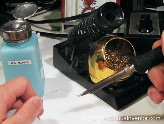
A common mistake we’ve seen in our classes–as well as from experienced ‘solderers’–is to clean the tip before putting the iron back in its stand. This habit leaves the tip exposed to oxygen in the air which works quickly to oxidize (basically rusting) the end of the tip. Almost all metals oxidize in air, and they do so much faster at higher temperatures. When your tip is thoroughly oxidized, it will look burnt, and no solder will stick to it. And if solder won’t stick to it, you won’t be able to create a “heat bridge” of solder between the iron and part, and very little heat will transfer.
To avoid this, coat the tip with a large blob of solder every time before returning it to its stand. While flux in the solder gradually eats away at the tip, oxidation will cause problems much faster.
You may notice that new tips actually come coated with solder. We’ve seen manufacturer documentation recommending that you hold solder against a new tip the first time you heat it up so that the tip gets coated as soon as it’s hot enough to melt solder.
Cleaning tip: If your tip is starting to look brown, and won’t ‘hold’ solder, or the solder acts like water on a freshly waxed car, you can help restore it by repeatedly applying solder and wiping it off. The flux in the solder acts like a cleaning against against the built up oxides. It may take 20 or more cycles of this to get the tip back into shape.
Controlling a Hand Drill with Arduino to Spool Solder
Here’s an instructable showing how to Control a Hand Drill with an Arduino / roboduino to spool solder. This may not be on the top of everyone’s project list, but a hand drill is strong enough to do a lot of tasks, so we hope this will be helpful to someone with another project idea,… maybe spooling guitar pickups.
Rather than use TRIACs to mess with the 120VAC, we found a servo was an easy and safe way to control the drill’s trigger / throttle. The setup also uses a home made optical encoder that triggers an interrupt in the arduino code. The code is available Solder_spooler_v3_pde, and contains some useful bits like lookup-table speed control, state machine menu system, and interrupt based speed sensing.
Use Multimeter Beep to Find SMT LED Polarity

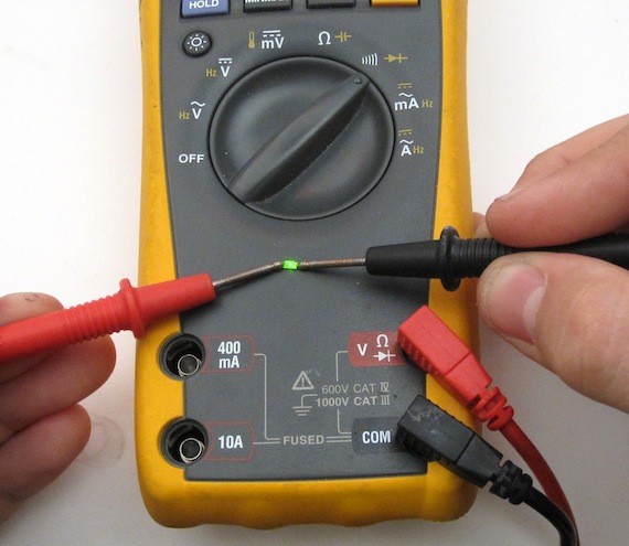
While SMT leds typically have a dot or small green line indicating their cathode, it can be hard to remember. A quick way to test a LED is by touching the ends with a multimeter in ‘Continuity Test’ mode. The multimeter generates a small voltage in order to detect a closed circuit, and this is enough to light the LED. Although we couldn’t burn out any LEDs with this Fluke, there’s no guarantee your meter won’t over-do the current, so we recommend doing just a quick touch, or putting a resistor in line.
Eagle vs KiCad
 Inspired by Steve Chamberlin’s post evaluating kicad vs eagle for someone new to both, here are some more opinions from the perspective of someone who uses both equally, (about 20 projects for both), but is certainly not an expert at either.
Summary: Eagle is more straightforward, has better library support of out of the box, and better community support (ladyada, sparkfun, etc.).
Kicad is free, and is maybe 1 or 2 revisions from being great.
Click the entry for our list of pros and cons:
Here is a random list of pros and cons:
- libaries:
- Eagle has great library support out of the box; sparkfun and ladyada’s libraries are great. Dealing with libraries in eagle is a little more straightforward. When you place a part in eagle’s schematic, you’ve already selected the layout package, where is with kicad, you need to use a 3rd program, CvPCB, to map the schematic symbols to the packages. Chamberlin pointed out that this is a pain when you’re trying to pick the right package out of a list of 400, but you can actually filter the list to the potential candidates using the filtered display.
- There are a lot of existing kicad libraries available, including a kicad port of the eagle libraries.
- For every kicad project, you have to add the symbol and package libraries in the project’s preferences before using them. With eagle, one “use” command and you’re good forever.
- Learning Curve:
- We give eagle a 6 hour time to go through a tutorial or two, and figure out how to make new components. Chapter 17 of the eagle tutorial (on libraries) is a must read. Kicad gets a 10 hour estimate to go through some tutorials and wrap your head around the libraries, along with getting past a few quirks. We’ve got a kicad tutorial if you’re looking.
- Highlighting:
- When you highlight a trace or component in eagle, it highlights in both the schematic and layout view. In kicad, there’s no way to highlight nets in the schematic view. This makes it hard to see when things aren’t connected. Sometimes components overlap lines in kicad schematic, but then aren’t actually connected in the netlists.
- Undo:
- The layout editor in kicad has no undo, except for undeleting parts. (this feature could very well be in the latest version).
- Routing:
- The shortcuts in kicad are great for quickly moving components and flipping between layers. You can also “hug” traces, which lets you places traces as close as your design rules permit. This helps to quickly make 4 lane parallel paths that zig and zag.
- Price:
- Non-profit: Eagle is free for 100 x 80 mm (4 x 3.2 inches) boards limited to 2 layers, non-profit. For $125 you can do up to 6 layers, 160x100mm (6 x 4 inches), also non-profit.
- Any use: Light (100x80mm, 2 layers):$49. Standard (6 layers, 160x100mm): $500 for schematic+layout. And there’s also pro for you 12 layer motherboard manufacturers. $1500 for everything.
- kicad is free and open source.
Conclusion: This is by no means an exhaustive list (more experienced users please weigh in!), but our guess is that eagle would be faster for someone just starting out until you want to sell your project or make that 7in+ long pcb, in which case getting past the kicad quirks is worth the effort.
Program-o-duino = Arduino + ZIF Socket

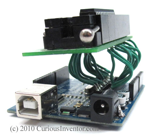
We program boot loaders on a decent number of ATMEGAs for our roboduino kit, which involves a lot of pin bending and IC pulling. To speed up the process, Oren transformed this arduino into a program-o-duino by soldering on a ZIF(Zero Insertion Force) socket. Now it just takes a quick pull of the lever to pop the chip in and out.
Voice of Saturn sequencing Moog Realistic MG-1
A demo showing off more of the capabilities of the Voice of Saturn Sequencer
Video: How to Solder QFN MLF chips Using Hot Air without Solder Paste and Stencils
This video demonstrates how to solder a QFN or MLF chip without solder paste or stencils. While solder paste and a stencil will product the most consistent results, this demonstration only uses an iron, flux, hot air and regular solder to get the job done.
Future videos will demonstrate how to use a solder paste syringe, as well as the recommended method of using a stencil.
Equipment used in this video:
- Aoyue 6028 Hot Air SMD Rework Station
- Tweezers for Surface Mount Devices (SMDs)
- Alcohol Dispensing Pump Bottle
- Chipquik No-Clean Paste Flux Syringe
- Liquid Flux
- Flux / Alcohol Bottle
- Desoldering wick/braid
- .02 SAC (lead free) solder
- Horse Hair Brush (ESD safe when wet)
- Hakko 50W Soldering Station
- 10X Magnifying Loupe