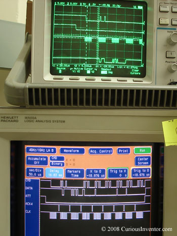
A logic analyzer isn’t the most common piece of equipment in a hobbyist’s shop, so we thought we’d write a small introduction about what it is and what it’s good for. A logic analyzer is commonly used to debug circuits where two or more chips are talking to each other, like a central uC interfacing with external memory, a peripheral camera or mp3 decoder. The main advantages over an oscilloscope are that more than 4 channels can be watched at the same time (sometimes more than 80), and that the logic analyzer can trigger / record right where it’s needed, not just on the first (or every) rising edge. For instance, you could program one to trigger and record data only after a particular byte sequence occurs. Read on for the (brief) basics of how to use a logic analyzer, what features to look for, some links to inexpensive analyzers as well as home-brew versions, and our attempt to digest a play station 2’s controller protocol.
small disclaimer: This is for a beginner and written by one… please point out errors and omissions!
Features and Basics of operation:
First, a small sanity saving feature: labels.
Instead of input 1, 2, 3,… the inputs can be labeled CLOCK, WRITE_ENABLE, CHIP_SELECT, etc., and multi-line buses can be configured to display hex values instead of binary. Reading a sequence of hex values (0x4D etc) is much easier than trying to decode stacks of square waves byte by byte.
State Analyzer or Timing Analyzer mode:
There are two modes that determine when a logic analyzer will sample:
In State Analyzer mode, the logic analyzer samples all the test signals on the SUT’s (System Under Test) own clock signal, so the analyzer sees data exactly the same as the test circuit.
In Timing Analyzer mode, the logic analyzer uses its own internal clock to decide when to sample. This mode provides more resolution, and is useful for making sure all the signals in the test circuit are transitioning correctly, ie, data is stable a sufficient amount of time before and after the clock signal. High end analyzers enable overlaying of both state and timing information to speed troubleshooting.
Triggering:
Besides having many more channels available than an oscilloscope, the other main advantage of a logic analyzer is its ability to record only the data of interest, even if it’s buried in the middle of a complex and long exchange. For example, a trigger could be designed to start recording only after seeing a particular bit pattern 4 times, followed by a delay, followed by another particular pattern, etc.
Newer PC-based logic analyzers make use of the PC’s infinite storage, so precise triggering isn’t necessary to capture the target communications. However, many argue that it’s better to setup a precisely targeted trigger in the first place to avoid spending time searching through megabytes of data. ECNasia mag has a good review of many inexpensive PC-based analyzers, some of which are even less than $200.
This hack-a-day comment listing includes lots of great links to parallel port and other home-brew logic analyzers.
Programming the Trigger:
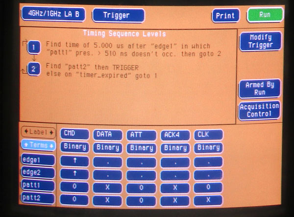
Doug Beck of HP has an excellent introduction to trigger programming and some common mistakes. The basic idea is to set conditions for when the analyzer should record. The conditions typically involve a sequence of events and not simply a rising edge. For instance:
- 1) wait until DATABUS = 0x3D
- then, if WRITE has 4 rising edges within 400 ms, goto 3, else goto 1
- 3) Record whenever ADDR = 0x56 (until record buffer full)
Each clock cycle of input data is tested against a step’s conditions until they are met, at which point the analyzer begins comparing input data to a new step in the chain. Note: after a level is completed, new input data is collected to test the next level. So if you wanted to check to see if ADDR=0x3D at the same time as DATA=0x32, both of these tests would have to be performed in the same level using an AND operator, not two different levels. The basic building blocks include timers, counters, Boolean logic , comparisons and edge triggers.
One very useful feature is the ability to automatically digest serial data (USART, SPI, I2C, etc.). This feature isn’t included in all logic analyzers, so be sure to look for it when purchasing.
This excellent Tektronix XYZ’s of Logic Analyzers ( / Advertisement for their $10k+ analyzers) says channel count is still important even for serial-only applications, because 32 bit instructions get re-mapped vertically across 32 different channels even though the data stream comes in on one wire.
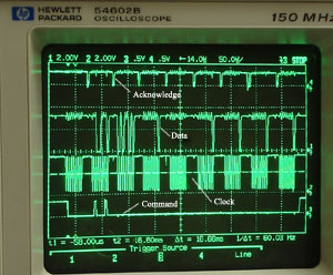
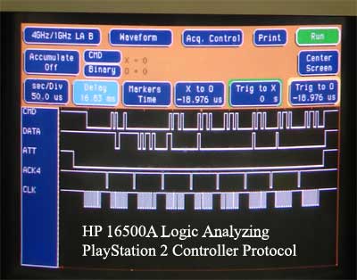
Finding the Configuration bytes in a PlayStation 2’s Initial Hand Shaking with a Controller:
In this case, we got away with sloppy wiring since the PlayStation protocol is relatively slow (500kb/s), but attaching probes can require careful consideration of how much the probes themselves will affect a circuit. Too much added capacitance will cause the rise and fall times of a fast signal to round, which could lead to erroneous readings. Many modern circuits are designed with special interfaces just for logic analyzer probes. This is especially helpful when there are upwards of 64 lines to watch.
Unfortunately, this particular analyzer did not have built in functionality for analyzing and triggering off serial data (only parallel), but we were still able to setup a trigger that found the configuration byte, and then recorded after a certain delay. The trigger uses edge detection and a timer to find a step of a certain size. Admittedly, a better example would have involved a parallel bus, but we were still able to get more out of the communication than with an oscilloscope.