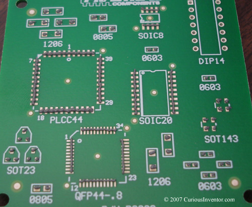
intro: This page will go over some of our first experimentation with solder paste and toaster ovens. Now, if you’re making several of the same board, the best route is to get a stencil and jar paste. Although slower, you can also apply paste with a syringe, and that is what we show in this guide. A double sided board with resistors, SOTs, QFPs, a PLCC and a fine pitch QFP will be soldered.
Equipment:
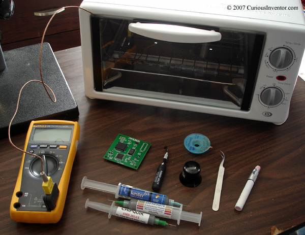
essential equipment: Solder paste, tweezers, toaster oven, a loupe, microscope or magnifying glass for inspecting finished joints (you may not need this for larger pitches), solder wick for fixing solder bridges / shorts.
other things: temperature indicating crayon (watching the solder melt works, too), vacuum pickup tool for placing parts (tweezers and fingers will get the job done, too), thermocouple to measure temperature. A couple companies sell toaster oven controllers–some of which you can simply plug the toaster straight into. These are nice for being able to setup a temperature profile and log temperatures, but in our experience the ovens don’t heat up fast enough to require any throttling by a controller. They would probably be more useful for complex boards with many layers, large ground planes or ones with BGAs.
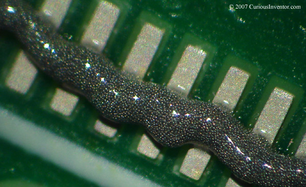
solder paste: Solder paste consists of small balls of solder floating within a gel-like flux. It’s an interesting animal that must be kept refrigerated to keep the flux from drying out. Also, the flux will slowly remove oxides from the metal–which is its job–but you don’t want it to get used up before the actual soldering operation; refrigeration also slows this process down. Some pastes have longer out-of-refrigeration shelf times than others, or may not require any at all–see the manufacturer’s recommendation.
Also note that the recommendations provided by manufacturers are geared towards industrial manufacturing with screen printing stencils and robotic dispensers. The industrial processes are designed to produce thousands of joints with minimal mistakes, so any small change in the paste rheology (how it acts under pressure) that causes an occasional defect would be unacceptable. But an occasional problem with a prototype can easily be touched up, so following the guidelines strictly may not be all that necessary.
Possible defects from dried out paste include slumping (the paste spreads out and causes bridges), solder balling, and clogging of stencils, which leads to insufficient solder coverage. Solder balling is when you find lots of tiny balls on your board that may come free and cause a short some day.
If you’re going to use a stencil, get paste in a jar instead of paste from a syringe. The syringe paste has slightly less metal to help it flow through a needle, whereas the jar paste is designed to work well with stencils. Many distributors will make you buy a plunger and needle to go along with the syringe. Digikey®, for instance, doesn’t even sell those, requires 2nd day shipping, and charges an obscene amount of money. There are lots of paste distributors; a little googling will save a lot of money. As for a needle size, I’ll recommend 22 gauge as a good starting place. You can control how much paste comes out by moving the needle over the pins faster or slower, too.
One last recommendation: get no-clean paste unless you have reason to believe your parts are very difficult to solder, and only then get water soluble paste. If you do use water soluble paste, the residues are conductive and corrosive, so be sure to clean them off with warm water.
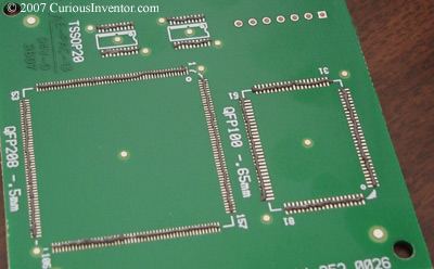
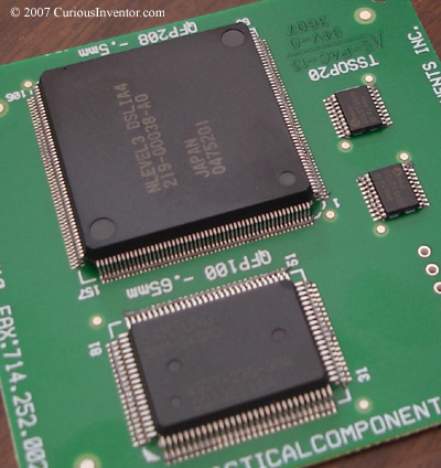
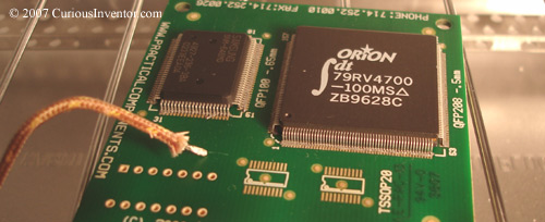
The first side: including a 208 pin, .5mm pitch QFP
We’re going to attach components to both sides. The components on the first side will be held on by surface tension when the 2nd side bakes. Do the side with lighter components first to reduce the risk that any will fall off. PLCCs are rather heavy compared to the number of connections, so we’ll do the side without one first.
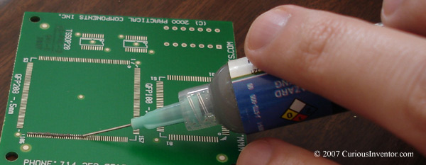
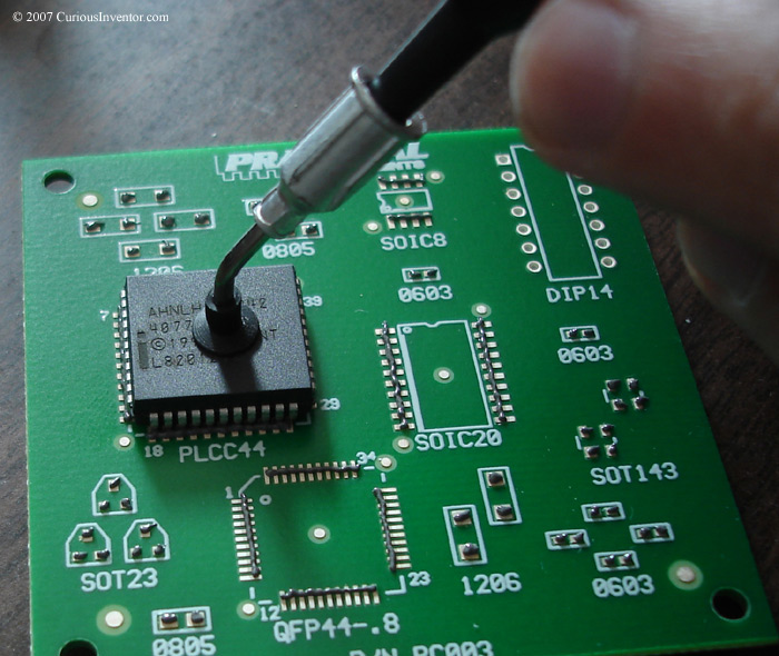
apply the solder paste: For fine pitch components, say .8mm and smaller pitch, just lay a bead of paste across the entire row. When it reflows, the paste will cling to the pads and connections and avoid bridging (for the most part). There’s a fine line between applying enough paste and adding so much that solder bridges are created. Some experimentation will probably be needed. For other components, place a small Hershey Kiss® of solder on each pad (see below for the 2nd side).
place chips on the paste: Using tweezers, fingers or a vacuum pickup tool, gently press components into the paste. If you smear the paste, wipe off the board area with alcohol and lint-free wipes and re-apply the paste. You want to avoid having bits of paste around the board since they will form into tiny balls that could come loose and cause a short.
Smaller components will snap into place when the paste melts, but larger components should be aligned as best as possible.
Baking the First Side:
what temperature and for how long? Paste and component manufacturers usually provide temperature profiles that give recommended and maximum values for the reflow process. If chips or boards are heated or cooled too fast, thermal stresses can break chips or warp boards. The paste will also not work correctly if heated too fast or too slow.
One question is just how critical the temperature recommendations really are. Most hobbyists or prototype builders aren’t trying to create 100,000 parts that last 5 years with no defects. But most industrial specifications are designed to provide that kind of performance. So, you might be able to get away with a lot of variation, but on the other hand, thermal damage may only show itself a week or month later–not on the first test. Also bad, the device might “sort-of” work, only producing bad results some of the time. So it’s probably best to follow the guidelines.
Reflow profile: As mentioned above, different components may have special requirements, but for a starting point, look at Kester’s standard reflow profile (this is for lead-based solder, they have a lead-free reflow profile, also).
There are 4 main zones:
- preheat: The assembly temperature is raised to 100-150 degrees C with a max rise of about 2.5 to 3.0 degrees C/sec. The main purpose of this stage is to evaporate solvents from the paste and slowly raise the board and components’ temperatures to avoid thermal shock and warpage. Recommended time: 60-120 seconds.
- soak: For a recommended time of 60-90 seconds, the assembly is slowly brought up to the solder melting (liquidus) temperature. This time allows the board temperatures to equalize and also for the flux to activate and clean off oxides from the metals.
- reflow: This is where the solder is actually reflowed, or melted. A time of 60-150 seconds is recommend, along with a max temperature of 240 degrees C for lead-based solder and 260 degrees C for lead-free. During this time the temperature should reach peak and come back down again to the freezing (solidus) point. You don’t want to immediately cool off the assembly as soon as the solder melts; a little bit of time is needed to allow the solder to properly bond with the connections.
- cool-down: To avoid thermal shock, keep the cool down rate below 6 degrees C / sec. Measuring board temperatures with a thermocouple, we found that everything cooled down much slower than this even with a wide open toaster oven door.
The above guidelines are based on an industry standard called IPC-J-STD-005 (not free). You can find the relevant portions of those specifications copied into this: PCB Land Pattern Design and Surface Mount Guidelines for QFN Packages. The Kester paste recommendations are slightly different. It’s probably best to start off with the lower temperature guidelines.
Again, all these parameters didn’t come into play since our toaster oven could barely heat up fast enough. We simply turned the toaster on full blast, waited for the solder to melt, counted to 15 and opened the door wide open. The board and components will have some impact on timing. Larger components will heat up slower, so be sure to make sure all the solder has melted before opening the door. If you’re using a thermocouple, place it next to the largest component. A chunk from a temperature indicating crayon will change colors permanently when its target temperature is reached. If used, place this by a large component, also.
Onto the 2nd Side:
apply paste
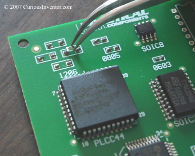
place components: Smaller components will self align during reflow, but larger ones should be carefully lined up.
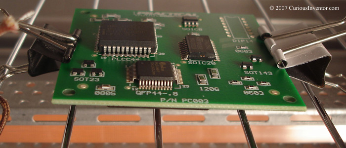
Bake the 2nd Side:
We used clips as stilts to hold the board up so the components already on the bottom wouldn’t touch the rack. We also tried using chunks of aluminum, but these drew too much heat away from the board, and the nearby joints didn’t reflow.
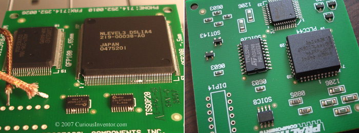
Results:
First, the bottom side components didn’t fall off.
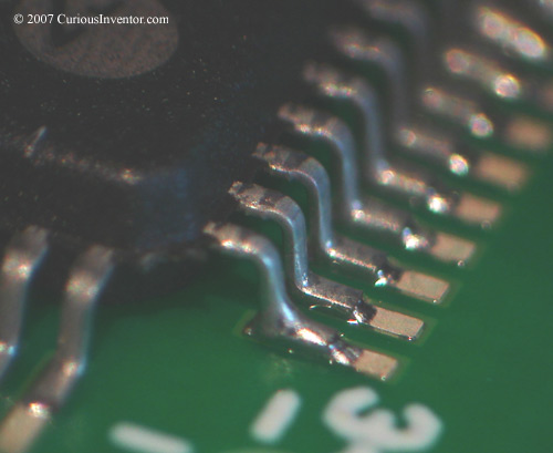
About 25 pins on our 208 pin, fine-pitch component bridged together. Besides a few other bridges, the other components turned out well.
Conclusion: If we had a stencil, this would be great, but hand soldering all these components may have taken less time than applying paste, placing components and then fixing bridges.
References:
- 10 tips for using Solder Paste from Kester A good primer for dealing with solder paste, although it’s geared towards industrial screen printing.
- Straight from the QFN package manufacturer, PCB Land Pattern Design and Surface Mount Guidelines for QFN Packages. It also contains a description of how to hand-solder QFNs, although their method doesn’t work unless the chip has connections that wrap around the bottom corner to the sides.