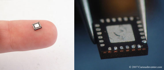
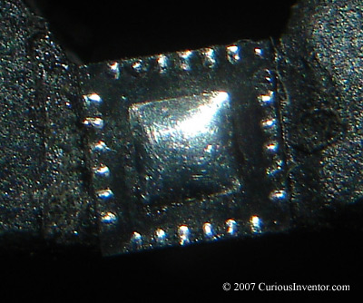
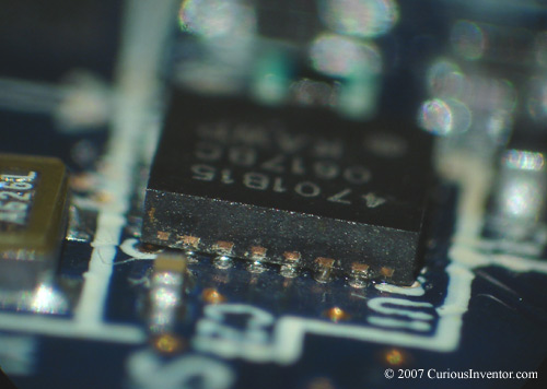
intro: QFNs are difficult because all the connections are on the bottom of the chip. Some versions have small extensions of these connections that wrap around the bottom corner and come up the edge a little. The perimeter connections (not the heat sink in the middle) on these can actually be soldered with a regular iron by applying lots of flux and touching each side and pad with a tinned iron. However, the version demonstrated in this guide only has small markers on the side, so hot air must be used to melt the bottom connections. Note that the best way to solder this chip is to use solder paste, a stencil and hot air (or a toaster oven or skillet), but we’ll be demonstrating a technique that doesn’t require either paste or a stencil.
New: Video Demonstrating Soldering a QFN using Hot Air without Solder Paste.
The video also talks about air temperature and speed, and flux type. The chip being soldered is a FM Radio from our .
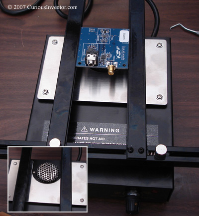
We’re going to show a hot air station ($250-$1000+) and an embossing tool ($25 arts and crafts tool for making raised ink decorations), as well as a hot-air pre-heater. You may be able to get by without a pre-heater, but it makes the job faster and less risky to the components and board. If you were doing a small one-sided board, you could also use a coffee cup heater, or, with a larger chip, a skillet set to about 100 degrees C.
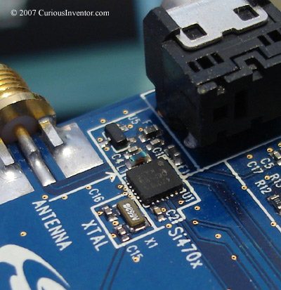
A 24 pin QFN from a SI Laboratories radio dev kit will be removed and then replaced.
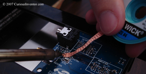
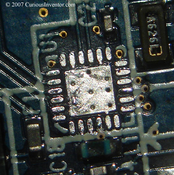
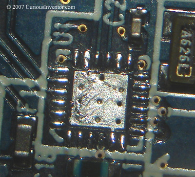
First, the original chip is removed by pre-heating the board and applying hot air using the same methods that will be detailed below. The pads on the removed chip and board are then cleaned by adding flux and using solder wick.
The heat sink has several vias (small holes meant to connect different layers on the board) that are used here to help draw heat away from the component and into the ground planes. While these help to keep the chip cool during use, they make it difficult to solder because heat from a hot air tool quickly dissipates into the board. A pre-heater is especially helpful if you’re going to solder the middle heat sink. However, many times it’s not necessary to solder this middle heat sink, and this is what makes soldering this chip especially challenging. So if you don’t need it, don’t add solder to it. And, if it’s your first time soldering a QFN, it’s probably best to skip the middle heat sink.
Before applying solder, clean off any old flux residues with alcohol and a brush, and then apply fresh flux.
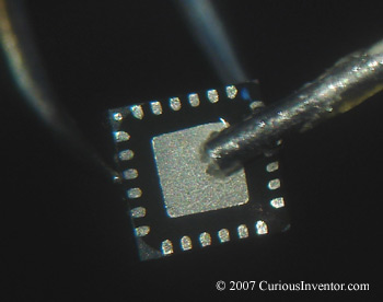
Apply solder to middle heat sink: To do this, tap a very lightly tinned tip against the fluxed pad until a small amount of solder wicks out onto the pad. The pillow of solder that forms should be very small, no more than 10 thousandths of an inch (1/3 of a 1/32″) tall. If you have calipers, you can check the pillow height by first measuring the original thickness and then comparing it the soldered thickness. If there’s too much solder on this pad, it will short to the outer connections during reflow. It’s better to have too little. Remove excess by applying flux and touching the solder pillow with a clean tip.
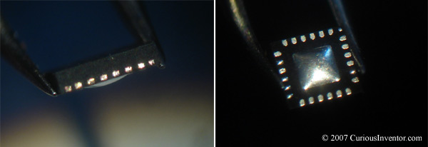
now tin the outer connections. Again, clean off old flux residue, add fresh flux, and touch a lightly tinned iron tip to the perimeter connections. Small beads of solder should collect on each pad. A microscope or loupe can be used to make sure each pad received solder.
tin the outer connections on the PCB: Do the same process for the PCB’s outer connections. Leave the middle heat sink free of solder.
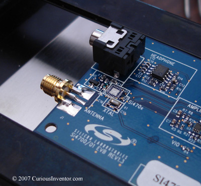
Pre-heat the board: Turn the pre-heater on and wait a few minutes. If you have a thermocouple or other temperature display, you want the board to be about 212-250 degrees F before continuing.
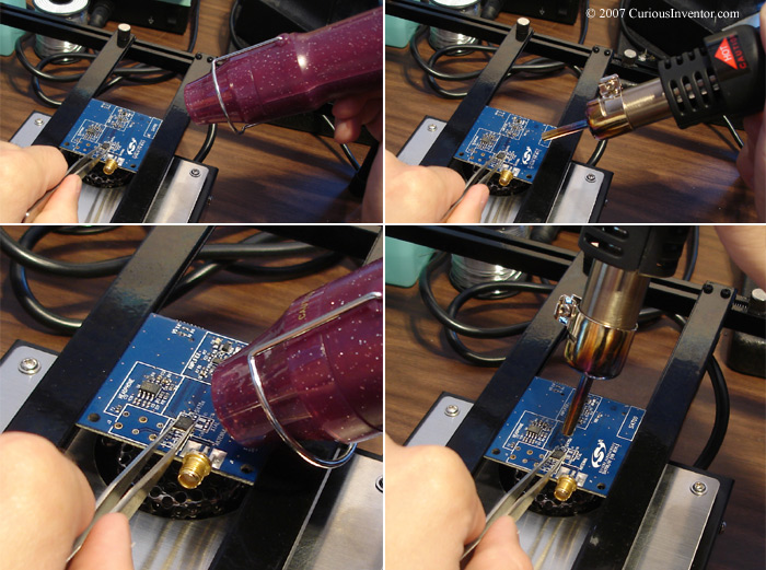
apply hot air: Holding the chip with tweezers, first apply hot air from a few inches away, and then move in to about 3/4″ away from the chip. Move the hot air in small circles. When the solder reflows, you should feel the chip drop into place. Let go with the tweezers. For this size of chip, surface tension will actually snap it perfectly into place unless there are shorts in the solder. Test to make sure it’s located by gently nudging the chip with tweezers–it should spring back into place.
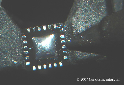
Check to make sure the chip is lined up correctly: A loupe or microscope can be used to make sure the markers on the side are directly over their corresponding pads. You should also be able to barely see connections under the chip.
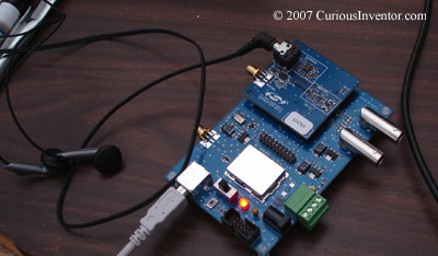
test your circuit: You can’t hear it, but our dev kit works once again with the re-soldered QFN chip.