This entry will take a dive into heat and temperature issues surrounding circuit layout design, including the effectiveness of the PCB itself as a heat sink when a voltage regulator’s heat sink is soldered directly to the board, and how to size trace widths for given current loads.

This article was written while writing a spec for the Roboduino Kit. One of the first questions is “How many amps can it deliver?â€
Our DPAK 5V regulator (https://www.st.com/stonline/books/pdf/docs/9614.pdf) is rated at 1.5A, but this amperage would likely require some serious heat sinking.
As a review, the total heat generated by the regulator is just the energy in minus the energy out. This is how linear regulators work—they turn excess energy straight into heat.
heat generated = (Vin-Vout)*I
(there’s also quiescent current in there which is the current used by the regulation circuity, but this is around 50mA, so we’ll ignore it for brevity).
So, if Vin = 9V, Vout = 5V, and I = 1amp, the heat generated would be about 4W.
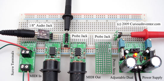
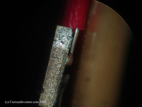
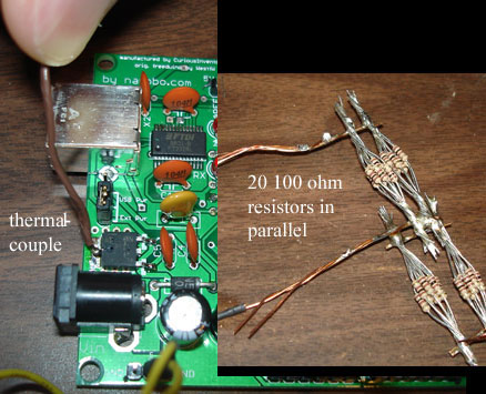
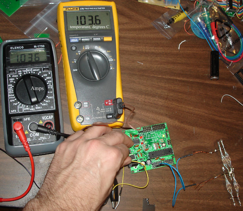
As it turns out, our board was only able to dissipate about 2W. A bundle of 20 1/4W resistors (100ohms, 10ohms total) was used as a dummy 1Amp load at 5V. A thermal couple measured regulator temperature at the solder joint. Current was measured before it entered the Roboduino’s input.
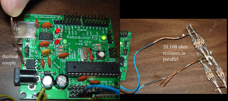
[setup pictures]
So, while the voltage regulator can handle up to 1.5Amps and 25-30 Volts on the input, any high amperage or large Vin would require some additional heat sinking, forced air or an extremely cold environment. The ambient temperature (Tamb) was about 24 deg C in these tests.
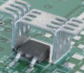
(There are, by the way, DPAK and other surface mount chip heat sinks that saddle over chips: www.aavidthermalloy.com/products/standard/surfacemount.pdf )
When Vin was 8 volts or higher, the regulator temperature rose to 125 deg C after a few minutes and its internal thermal protection circuitry shut the regulator down.
How Much Heat Can the PCB Dissipate from surface mount components (SMT)?
Robert Kollman of TI has a great article on Power Supply Layout Considerations (https://focus.ti.com/lit/ml/slup230/slup230.pdf) that covers heat transfer through the board and its traces, (as well as lots of useful info on parasitic inductances / capacitances, ground design, and voltage losses through traces).
We’ll summarize the highlights and conclusions, but first some basic structure on how these types of heat transfer problems are thought about and solved:
In most cases, there is a temperature that will break something: either the pcb board material (FR4) will break down or a device will become permanently damaged or shut down. In the case of our voltage regulator, it shuts down at 125 degrees C.
The next question to ask is “What will the ambient temperature be in which the device operates?†The best heatsink in the world won’t help if it needs to operate in the desert and components fail at desert temperatures (or automotive: -40 to 125 deg C).
The final operating temperature will be:
T_device = T_ambient + Q*R, where Q is the heat generated and R is the total thermal resistance between the device and the outside air.
Rearranged, (Td-Tamb)/R = Q, which is analogous to V/R = I, where voltage is T and current is heat.
So, in the design stage, you’ll need to make a best guess at what the ambient temperature will be, and then you can calculate a target thermal resistance. Typically “trace width calculators†and other guidelines are written in terms of an “acceptable temperature rise,†(Td-Tamb).
In the case of a CPU with a heatsink, you would add up the resistance of the “junction to case†(resistance from the actual heat generator to the outside of the package) + the heatsink interface resistance (thermal paste, negligible for soldered joints) + the resistance of the heat sink to the surrounding air. The device’s manufacturers would provide all of these numbers.
However, when a component is soldered directly to a board, there are no easily-looked-up numbers past the “junction-to-case resistance.†You’ll have to estimate how much resistance there is to heat traveling through the board (conduction) and also into the air (convection).
To get a frame a reference, the convection thermal resistance of still air is about 166 C/W sq in, or in words, 1 Watt going through a square inch will cause an increase of 166 deg C in temperature. (that number may be a little conservatively high). So, say you wanted to keep your temperature rise at 80 deg. C (would put our device a little over boiling), @ 2W, you would need ~4 square inches. But you also have to take into account the resistance the heat encounters while spreading out.
An interesting note from Kollman is that heat travels 30 times more easily through 1oz (1oz / sq. foot, 1.4mils thick) copper than .06†FR4, 60 times when 2oz copper is used. So the best way to spread heat out is to employ large copper planes.
What about planes on both sides of the boards? Despite the high resistance of the FR4 material, the large surface area moves heat somewhat easily between top and bottom planes, more than 20 times easier than the heat transfers to the air via convection (p. 4-14). So planes on both sides will help immensely. A handful of vias can help distribute heat, too. Twelve 17mil sample vias equate to the same resistance as 1 sq. inch of bottom-to-top plane resistance (8 deg C/ W in the paper).
One other factoid about heat spreading through planes is that gaps significantly block transfer, so continuous planes are most helpful.
Kollman simulates a small 5mm circular 2W heat source on a board with copper on the top and bottom (2oz). Most of the heat was dissipated within the first inch around the device. The final simulated resistance was around 15 deg C/W, but Kollman says practical experience places this value closer to 20 or 30 deg C/W.
In our testing of the Roboduino, which has copper fills on both sides of the board, many vias connecting the planes at the regulator, but also lots of traces cutting up the planes, we got measured about 38 deg C/W with the following conditions:
Tamb = 24 deg C Tdevice ~= 100 deg C Q (heat) = 2W Total resistance = (100 – 24 ) / 2 W = 38 deg C/W.
We estimate that a similar thermal resistance would be found on the Arduino Diecimila and Freeduino, after which the Roboduino was closely modeled.
One final note is that some heat will also leave via radiation. Kollman estimates radiation to be about half as effective as convection (in a “black body†room), but he says that most engineers use this as a margin of safety rather than incorporating those calculations.
Trace Width Calculations: How Wide for a Given Current?
The Roboduino board also supplies power straight from the voltage input to various pins so that servos can be driven at Vin, not 5V. We needed to design the traces powering those pins so that they could carry sufficient current (4-5 amps).
https://circuitcalculator.com/wordpress/2006/01/31/pcb-trace-width-calculator/ is a useful calculator for calculating necessary trace widths (and also great Q&A’s in the comments). You will, however, need to decide what an acceptable temperature rise is before using the calculator.
Previously, our voltage regulator would shut down at 125 deg. C, but in the case of a trace, the limiting factor is damage to the pcb material itself. Judging from comments posted around the internet, it seems that most people use a 10 deg “acceptable temperature rise†when they want to question of whether the device will work or not. Some others from industry claimed to have used 30 deg C for products.
If you are fairly sure your device will not operate in an ambient temperature greater than 50 deg C, (122 deg F), 30 deg. seems excessively conservative.
Our board is FR4, which has a Tg (glass transition temperature) typically between 115 and 125 deg. C (this depends on the exact materials used by the manufacturer). What is the glass transition temperature? According to https://www.arlon-med.com/Everything%20You%20Wanted.pdf , it’s roughly when the material changes from a hardened state to… something less hard, maybe rubbery. The article points out two consequences of reaching that temperature:
The bond strength between the resin, laminate and copper foil becomes weaker, so pads and traces are more likely to lift. Also, the coefficient of thermal expansion (how much larger things get for each degree increase in temperature) goes up dramatically, which can cause plated through holes and via barrels to crack. Finally, prolonged exposure to higher temperatures can oxidize the hidden side of traces, which further weakens their connection. Chet Guiles (author of above link) seems to indicate that operating “close†to the Tg is a bad idea. There is also the RTI (relative thermal index), which is published by the UL. This number is supposed to be the point where the device will operate for 100,000 hours and still retain 50% of its original properties. It’s unclear how to go from either of these numbers (Tg or RTI) to a “safe†acceptable temperature rise.