Description
Spec sheet: here
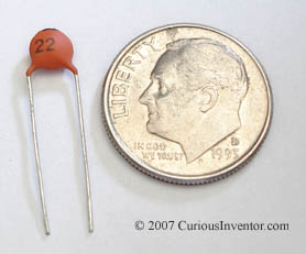
Here are 22pF ceramic disc capacitors commonly used with this crystal to provide a clock source to micro-controllers.
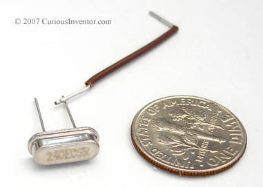
When installing, be sure that the case does not make contact with any other conductors; ie, don’t push it all the way flush with the board.
+-5ppm (parts per million) per year aging drift.
About crystals: There are several different ways to provide a clock source, including crystals, oscillators, RC circuits, and resonators; this article gives a good comparison. Crystals offer a good compromise of low cost, high accuracy, good temperature stability, and low power use.
They are typically used in what’s called a "Pierce circuit" with microcontrollers that has two other capacitors tied to ground on either side of the crystal. The value of the capacitors affects the circuit’s frequency. Crystals manufactured for use in this type of circuit are parallel crystals and come pre-compensated for a certain "capacitive load." The formula that relates the crystal’s capacitive load and the capacitors used in the circuit is: CL = (C1*C2)/(C1+C2) + Cs (stray capacitance in leads and circuit board). Many guides suggest Cs is usually around 5 pF, but the Microchip spec sheets seem to assume it’s 12.5pF.
PPM (Parts per Million): This is like a percent error (1000 PPM = .1% error), and is convenient for calculating error with crystals. 5ppm on a 4MHz crystal = 5*4 = 20Hz possible error. Most microcontroller applications don’t require too much accuracy, 100ppm is fine. If the parallel capacitors don’t match the crystal’s capacitive load exactly, they will pull the frequency, but not much. This offers more info about pullability and crystals in general. It seems to indicate that on a 20pF CL crystal, you may get 16ppm/pF error between the anticipated load and actual.
A Microchip application note that talks about crystal design considerations for microcontrollers.


Reviews
There are no reviews yet.