Description
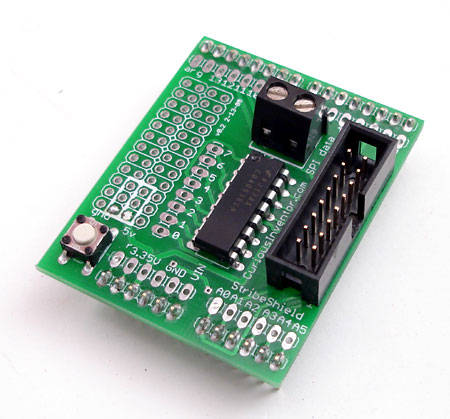
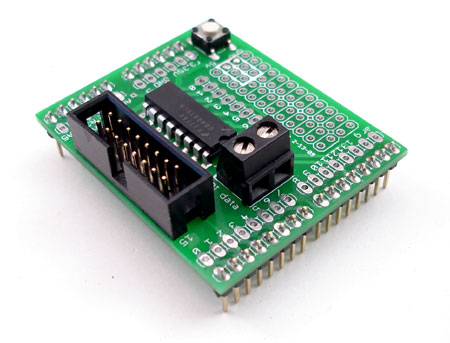
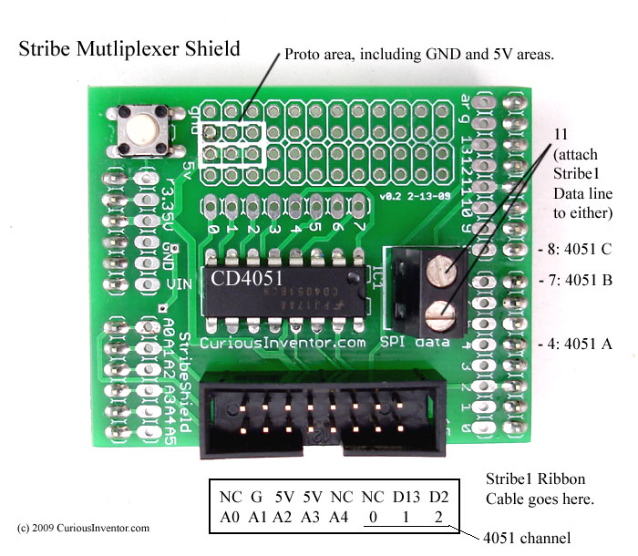
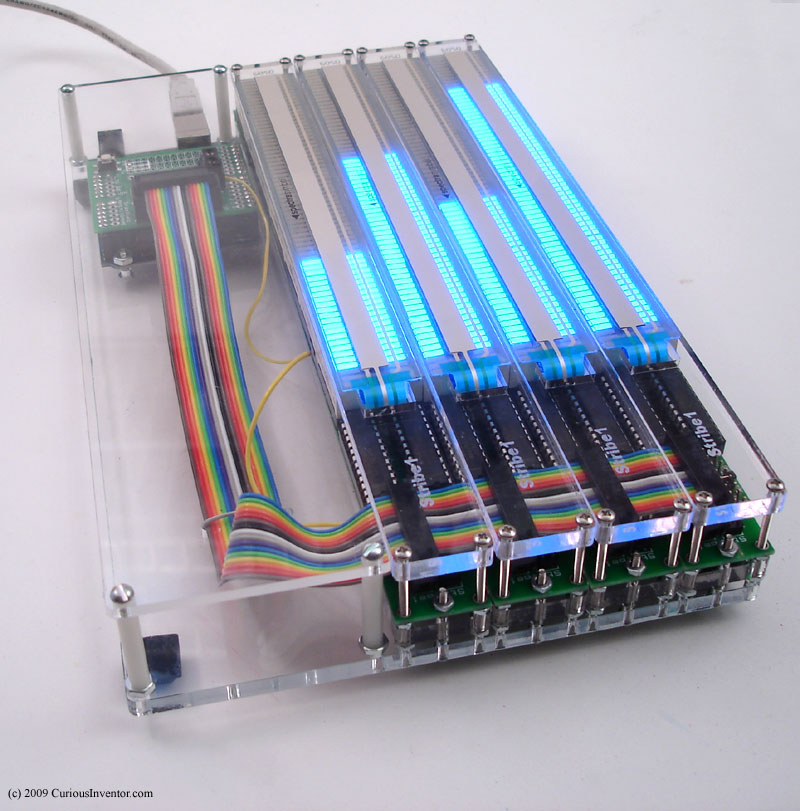
Stribe1 code rev E and later already incorporates the code to read more than 5 Stribe1s through this shield. Attach the ribbon cable to the 2×8 header and the data line to one of the screw terminal positions (both are connected).
How it Works:
The CD4051 is a switch that lets you connect one pin to one of 8 other pins. This way you can read 8 lines with only one pin on the arduino, giving a total 13 analog inputs when using the stribe_shield. Three 4051 pins control which of the 8 pins connect to the common I/O pin. Set your Serial Monitor to 57600 baud and connect analog signals to A0 – A4, and holes 0-7 along side the 4051 chip. Don’t attach anything to digital pins 4, 7 or 8–they’re used to control the 4051. Also the 5th analog pin connects to the 4051.
Arduino Code:
Example arduino code that reads in 13 analog values and sends them back over the serial port (baud 57600).
Eagle CAD Files and Schematic:
Stribe Shield Eagle CAD files released under the TAPR Open Hardware License. stribe_shield_v0_2.pdf schematic

Reviews
There are no reviews yet.