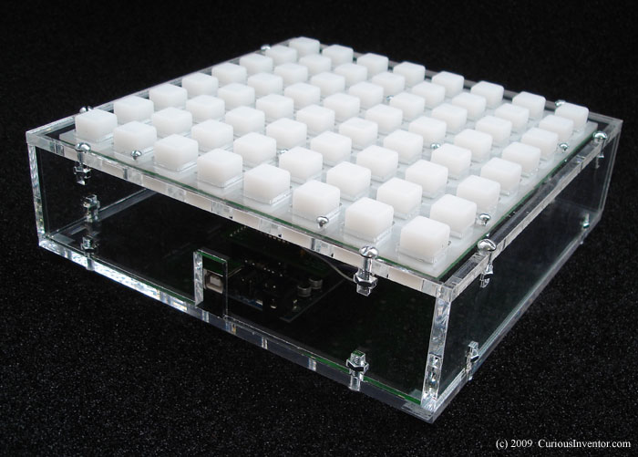
Both black and clear acrylic arduinome cases can now be ordered. Our first batch is very limited, but more will arrive soon. This post will detail the building and programming process.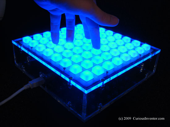
Building an Arduinome
This guide largely echos bricktable’s (thanks!), with some added bits and pieces.
Parts list:
Both our black and clear acrylic cases come with the following:
- (16) 8-32 screws
- (16) 8-32 nuts
- (4) rubber feed
- (2) 4-40 standoffs
- (1) 2-56 screw (for small arduino mounting hole)
- (5) 2-56 nuts (for small arduino standoff and nut)
- (20) 4-40 .5″ screws for buttons
- (20) #4 lock washers
- (22) 4-40 nuts (for standoffs and button screws)
You’ll also need:
- arduino Diecimila (or newer versions that accept shields)
- unsped shield
- spark fun buttons and pcbs
- (64) bright LEDs (1000mcd blue LEDs shown) mouser: 604-WP7104PBC/A Both 3mm and 5mm LEDs with .1″ lead spacing fit. Standard LEDs will barely show through the buttons, even in low light.
- (64) small-signal diodes
- 8-Bit Shift Register. mouser: 512-MM74HC164N
- 8-Bit PISO Shift Reg, mouser: 511-M74HC165
- 10uF cap
- (3) .1uF caps
- 10 Pin Common Bus Resistor Network, mouser: 266-100K-RC
- (2) 2×8 headers
- (2) 16 pin IDC sockets
- ribbon cable
- (1)single row male headers
- 24 pos. socket, 14 pos. socket, 16 pos. socket
- MAX7721 or MAX7719
- current limiting resistor, see the forward voltage chart here
Starting with software so we can test everything before installing all the screws.
Software: Setting the USB Serial ID, Firmware, ArduinoSerial, Monome Software
Outline: A program called ArduinomeSerial lets monome apps talk to the arduinome. In order for AruinomeSerial to recognize the arduinome, your arduino needs to have a new serial ID programmed into the FTDI USB-to-serial chip, as well as arduinome serial firmware.
Setting the USB Serial ID on the arduino:
- Plug in the arduino
- Download MProg and run it (PC only, any Mac solutions?).
- Tools –> Read and Parse
- In the “USB Serial Number Control” box, check “Use Fixed Serial Number” and type in a number like “a40h-001” or any variation on “a40h-xxx”. a40h- is the important part.
- File–> Save As… whatever you like.
- Device Menu –> Program
- It should respond with a “programmed device with…” message.
- The monome forums have more info on this process.
Load the arduinome firmware:
- Download the arduinome firmware. Note: it may look like only the firmware is available, but if you click “arduinome” under package in the download page, you’ll find the ArduinomeSerial program.Download ArduinomeSerial, too.
- Use arduino v11 to program the firmware.
- Run ArduinomeSerial. If it lists your serial number under the “Device Settings” box, it found the device.
Hardware: Wiring the button pcbs, Soldering the Unsped PCB, Building the Case.
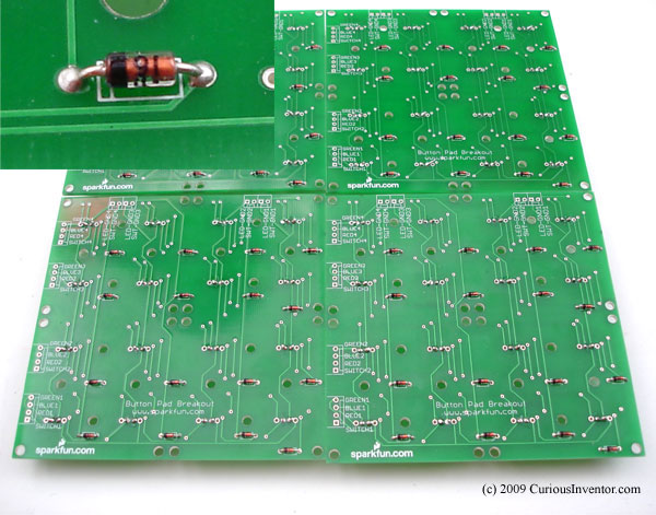
Install diodes: Make sure the line on the diode matches the silk screen. Trim their leads close (flush cutters!) so they don’t interfere with the buttons.
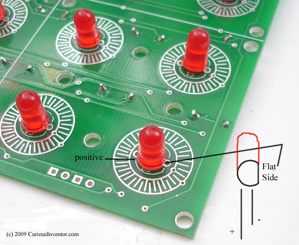
Install LEDs: Ground (shorter lead) is the 2nd hole from the flat side. The 3rd hole connects to the “Blue LED” line.
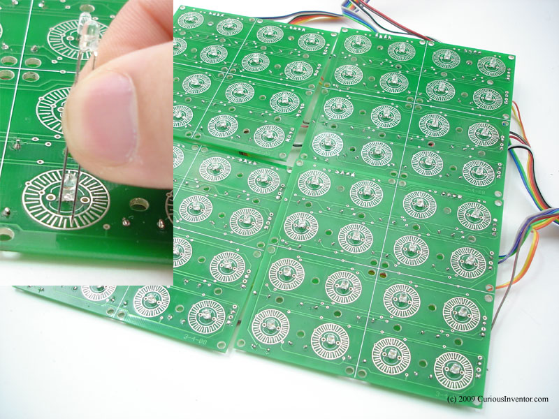
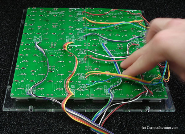
Wiring the pcbs: Feel free to do this how you like, but we cut 5″ & 10″ segments of ribbon cable, stripped both ends of the short segments and twisted them together with the stripped ends of the longer segments. Follow the wiring diagram below, and for a more complete schematic, check outcbit’s. It’s not a bad idea to beep-test (check connection) a few lines between the button pcb and the actual sockets on the unsped pcb.
Note: each blue & switch pair is flipped.

Click image for a larger version.
Solder Components to the unsped pcb:
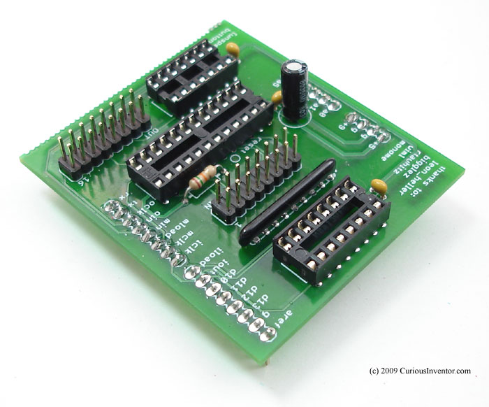
Note: see here for info on choosing the current limiting resistor. We used a 15k to limit current to 30mA per LED, which was chosen based on the 3.2 forward voltage drop of our LEDs.
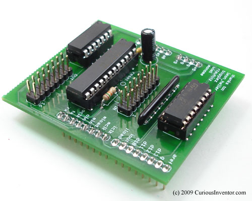
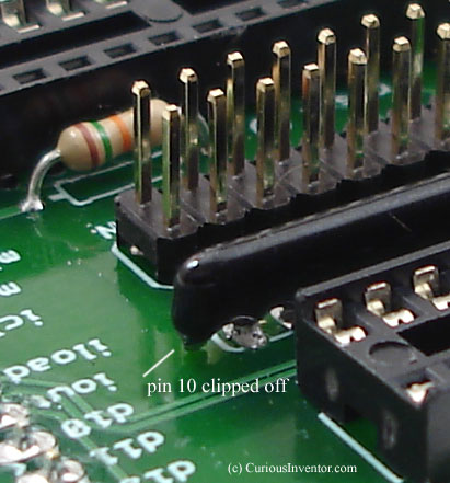
Clip the the 10th pin of the resistor package–only the first 9 are needed. The package is notsymmetrical, don’t clip pin 1.
Note: we broke off the break-out board because we’re not using it in these instructions.
Start building the case by attaching arduino to base:
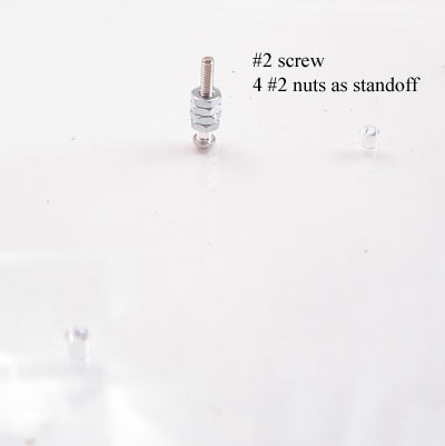
First add the #2 screw and 4 #2 nuts to act as a standoff.
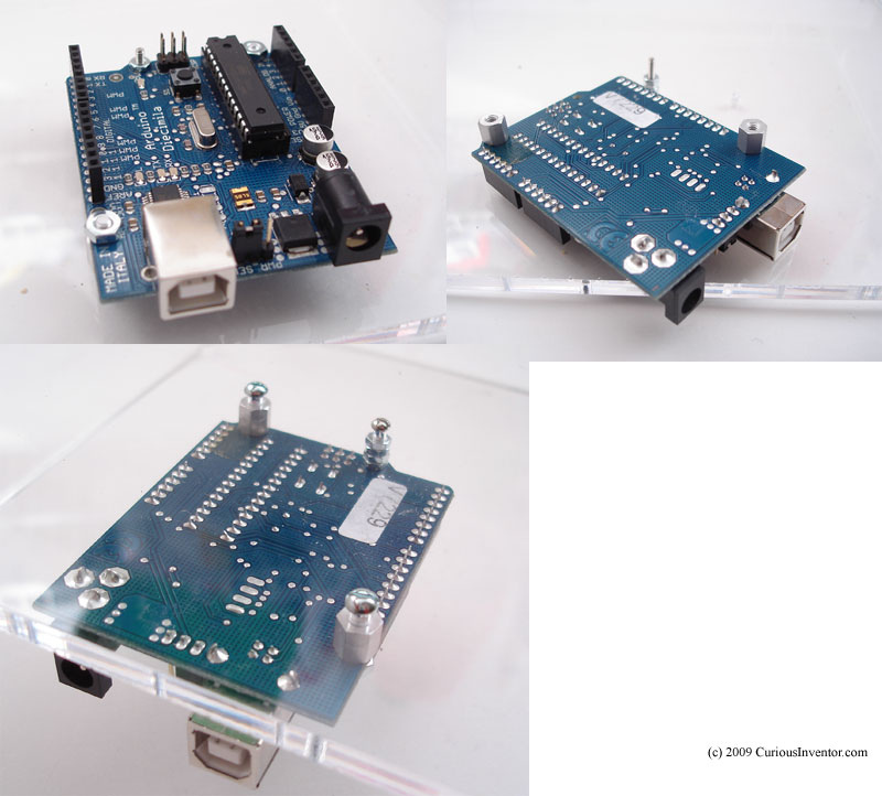
Now attach the standoffs with nuts to the arduino, and then use the shorter 4-40 screws (3/8″) to secure the 4-40 standoffs to the acrylic base plate.
Put buttons in top face:
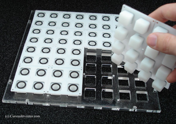
Lay the button pcbs on the buttons, secure each with one screw in the middle.
Although not pictured, install the 4-40 lock washers under each nut.
Wiggle to make sure they’re seated correctly.
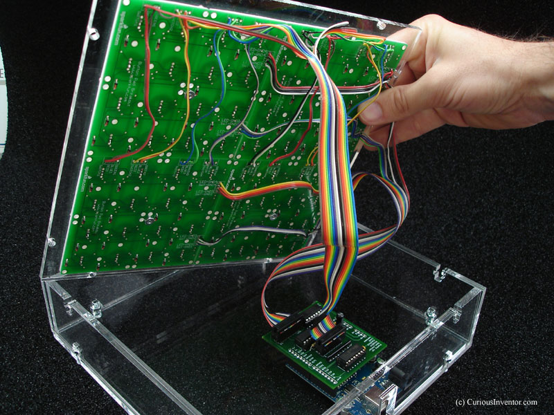
Before completing the case, download the monome_base apps and run monome_test:
Plug in the shield, IDC sockets, and USB cable. See the getting started instructions for a first test. If everything works, proceed ahead.
Continue installing the rest of the 20 button screws, washers and nuts.
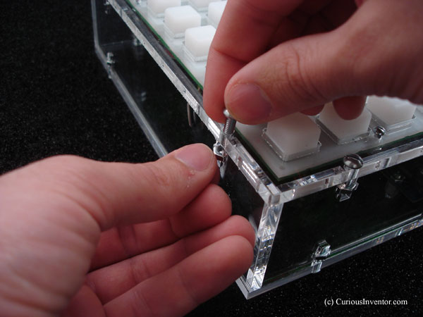
Begin installing side panels:
Slide a nut into its slot, and then insert the screw through its corresponding hole.
Finish two sides, and then begin installing the top.
The picture shows all 4 sides installed first, but by doing only two sides first it’s easier to grab nuts that may fall inside. Also, the sides of the acrylic have a slight angle, so they’ll tilt a small amount if only the top or bottom is attached. Counter this by holding the side in place while securing the top.
When everything is in place, tighten down all screws.