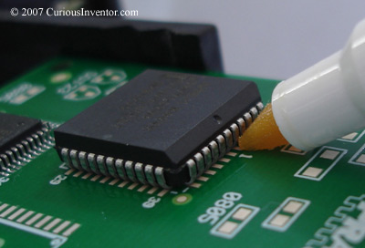
The leads on a PLCC are called J-leads due to their shape. A brief summary of the steps is to flux the pads, tack two opposing corners, add more flux and then solder the rest of the pins.
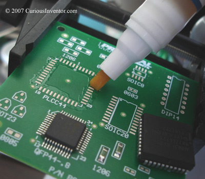
First, flux the pads.
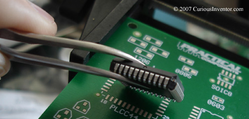
Then align the part, keeping in mind that pin 1 on PLCCs is in the middle of a row, not a corner.
Place a small amount of solder on a clean tip, and then touch a corner pin and its pad while holding down the chip. You may want to add some flux to this pin beforehand. The next step is to tack an opposite corner, but be sure to re-check the alignment first. Once two pins are soldered you’ll need to completely remove the chip to make any adjustments.
Add additional flux to the pins of the PLCC. The flux from the wire solder may be enough to skip this step, however.
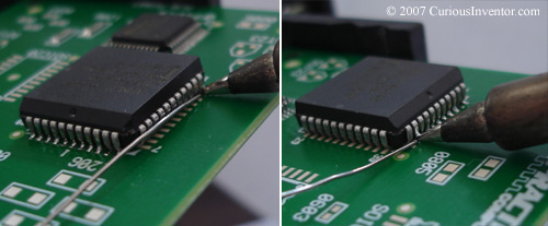
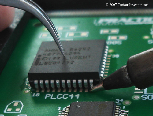
Lay a piece of solder against the bottom of the leads and the board; .02″ diameter solder works well and is shown on the left. Now successively press the solder into each one of the pins. Heat each joint long enough to allow the solder to completely wick around to the back of the pin, but no longer.
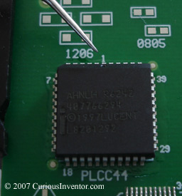
Finished Results:
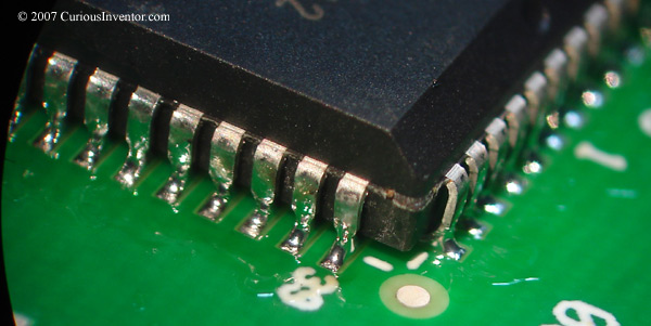
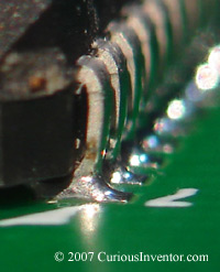
The goal is to have the solder wick all the way around to the back of the pin, and have a smooth filet (or curved ramp) connecting the pin to the pad in the front. The most important aspect is that the solder looks like it wetted (adhered to, clung to) the metal. Lead-free solder and some types of flux with lead-based solder will leave duller joints; this is OK.