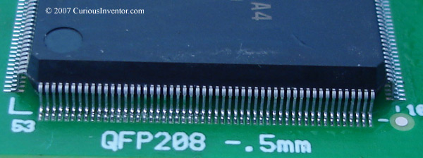
(QFP: Quad Flat Pack)
The steps for soldering both of these chips are the same: add flux, tack some corners, add more flux and then solder the rest. We also use the same soldering iron tip for both–even the .5mm pitch. The leads on QFP’s are called gull wing leads.
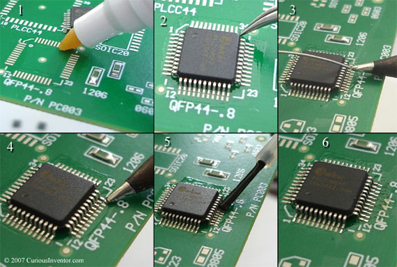
Soldering a QFP:
-
- flux the pads: This pre-fluxing will help hold the chip in place, and also ensures that the pads receive sufficient flux.
- align the chip
- add a small drop of solder to the end of a clean tip: This is the key to both tacking a corner and soldering the rest of the pins. You want a small drop of solder to hang off the end of the tip. Too much and you’ll create bridges or shorts between the pins.
- tack two opposite corners: Gently slide the tip up against the toe of the corner pin. All you’re trying to do here is here is bring the solder drop in contact with the pin. Once they touch, surface tension will take over and wick the solder around the pin. This is the magic of surface mount soldering. Before tacking another corner, be sure to recheck the alignment and reheat the first pin if necessary. Once multiple pins are soldered, it’s almost impossible to make adjustments without completely removing the chip. Even with solder wick, surface tension will retain some amount of solder under the pin.
- add more flux on top of the pins: You may want to do this before tacking the corners and skip the initial pad fluxing.
- continue soldering the rest of the pins: Use the same technique to continue soldering pin-by-pin. With some practice, you can solder an entire row of pins at once by dragging a larger blob of solder over the toes–this is called drag soldering. Some of the tips that are specially designed for this technique are called “hoof” and “mini-wave” tips.
-
- Industry specifications (IPC J-STD-001) indicate that there should be a fillet at the heel of the pin that smoothly connects the pad to the pin. So, you’re basically looking to make sure enough solder wicked around to the back of the pin, and that it looks like it adhered or clung to the metal. Lead-free and some fluxes for lead-based solder won’t look shiny, but this doesn’t necessarily mean the joint is bad.

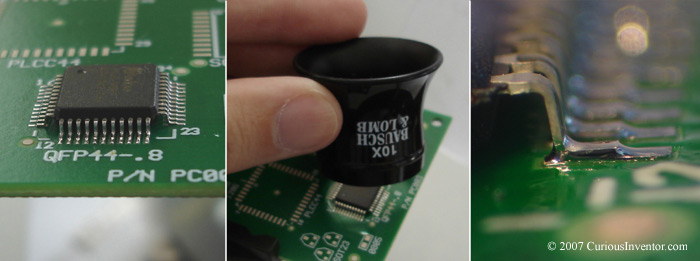
Soldering a Fine-Pitch QFP (.5mm Pitch):
We use the exact same steps to solder fine pitch components. For pitches down towards .5mm, using the loupe or some other magnification is more important for finding solder bridges or pins without enough solder.
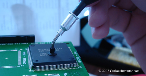
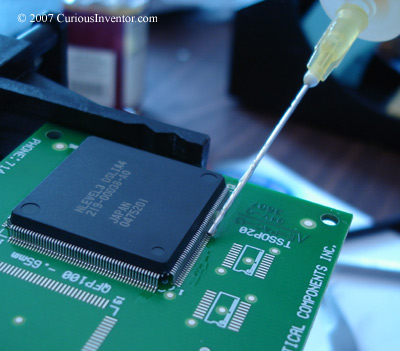
First flux the pads, place the chip and align it with tweezers as usual. You’ll probably need to use the loupe to ensure the pins are centered on their pads. The picture shows a vacuum tool being used, but fingers and tweezers work, too–just be careful not to bend the pins. If you do, an Xacto® knife or a dental pic can be used to straighten them out again.
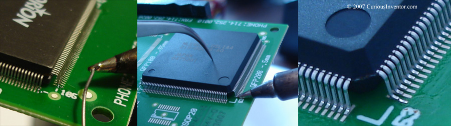
You’ll probably want to tack more than just two corner pins since two pins this small can easily be bent if the chip is bumped. Place a very small drop of solder at the end of a clean tip, and gently touch the toe of a corner pin. The right pane of the above picture shows just how little solder is needed.
Add more flux on top of the pins.
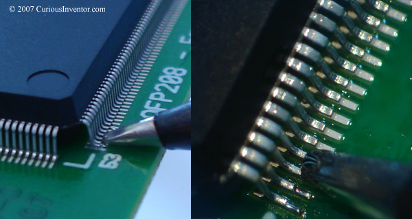
Continue soldering the other pins similarly. The pictures show just how close the soldering iron gets. Drag soldering can also be used, but it’s much harder to avoid creating bridges without a microscope on this pitch.
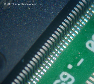
Note how little solder is on each pin.
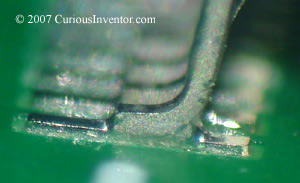
Again, the goal is to have a fillet at the back of the pin. Industry specifications state that the rear fillet should reach up to at least the height of the toe of the pin.

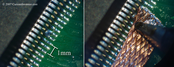
Solder bridges can be removed with solder wick / braid.
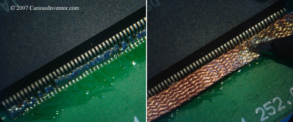
The Flood and Wick Method:
A very popular method is to flood the pins with solder, and then use wick to clear off all the bridges. This works because surface tension retains some amount of solder under the pin no matter how long the wick is applied. Industry folks don’t recommend this technique as it’s very easy to overheat the board or component. Also, solder wick has a tendency to freeze on pads or leads, and if you’re pulling on the wick when this happens, the pad or lead can easily be torn off. Finally, the wick can leave behind very little solder in the joint, which leaves the connection susceptible to breakage during vibration or temperature changes. If you use this method, be gentle and try to limit how long you apply heat to the part and board.