Desoldering

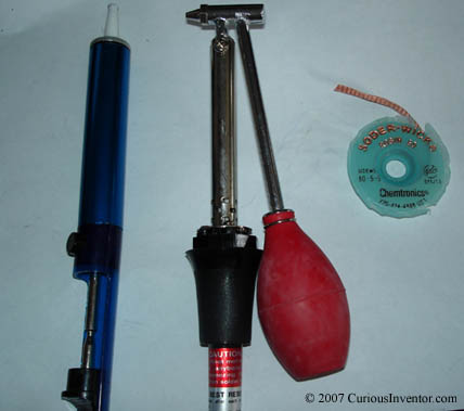
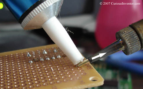
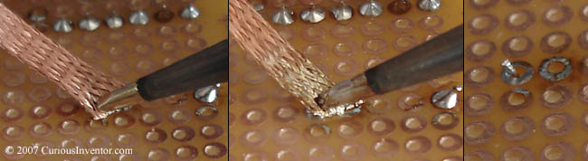
The three most common inexpensive ways to remove solder include a “solder sucker”, solder wick, and an iron with an attached desoldering bulb.

Desoldering tools


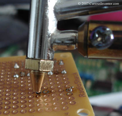
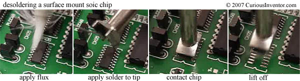
Surface mount desoldering: Surface mount chips are especially hard to desolder because it’s very difficult to completely remove all the solder pin by pin, and avoid overheating the board and lifting a pad. Professional shops use expensive hot air guns or special tips (shown below) to heat all the joints at once.

Desoldering a SOIC

There are fortunately a few cheap ways to desolder surface mount chips.

  • ChipQuik provides an interesting solder that when melted over existing joints produces a new low-melting point alloy (under 200 °F) with a much longer solidification time. The longer solidification time enables you to melt all the joints at once and then flick off the chip.
  • There are many guides for making a DIY hot air gun with the RadioShack® desoldering iron and a fish tank air pump. Engadget has one of the better how-to guidesHere and here are some more plus the supposed original.

Protection

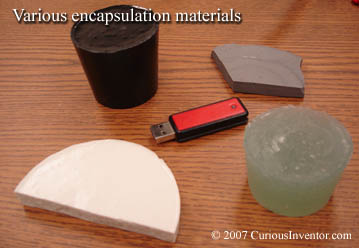
You may want to add what’s called a “conformal coating” to the connections to keep dust and moisture away. This is basically a clear coating that conforms to the surface of your parts, and there are many different kinds. In some military applications, they actually embed circuits in a solid chunk of epoxy or silicone to safeguard them. Note that if the circuit needs to be repaired, these coatings can be very difficult to remove.

Various encapsulation materials

Clean Up

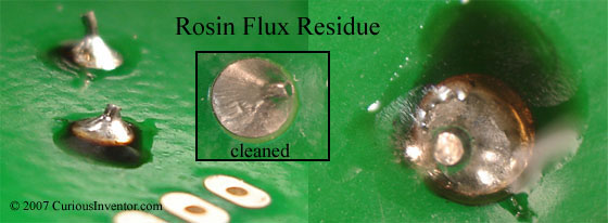
Most manufacturers will clean off residues from any flux that isn’t labeled “no-clean,” despite flux datasheets like Kester’s that say even some of the more active fluxes do not need to be cleaned. For short life-span hobby projects, it probably doesn’t matter unless you’re using a solder/flux labeled “organic” or “water-soluble”–these fluxes leave behind very aggressive acids that will quickly eat away circuits. Cleaning may be necessary if you’re applying a protective coating that won’t adhere to flux residues. Finally, some rosin residues are tacky and may attract dust that can short a circuit.

The fact that a flux is made from rosin doesn’t tell you much about how strong it is or whether it should be cleaned. What matters is how concentrated the mix is and how much acidic (halides) activators were added. RadioShack® doesn’t supply any information on the flux in their standard rosin-cored solder, but it’s probably weak enough that the residues do not need to be cleaned off.

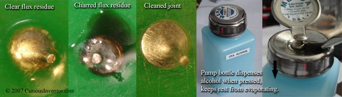
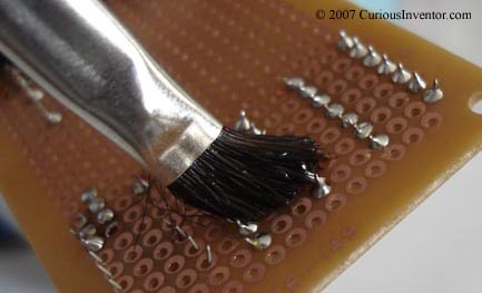
Isopropyl alcohol works decently on rosin-based residues, but clean shortly after soldering because the residues quickly harden. Use water for water-soluble fluxes. This pump containing bottle dispenses a little alcohol when you push down on the top with a brush, and keeps the rest from evaporating. If you are going to clean, make sure you wipe up the remnants with a lint-free cloth–don’t just spread them around the board with a brush and alcohol.

Cleaning flux residues

Cleaning with acid brush

Heat and Solder the Joint

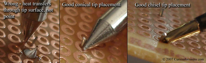
  • Heat the joint: Place the iron tip so that it touches both the component lead and pad–the goal is to get as much surface area contact between the iron tip and joint as possible. Almost no heat will travel through the point.

    Tip placement

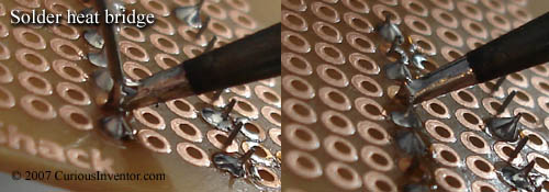
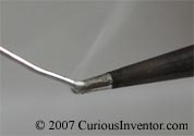
  • Make heat bridge: Add a small amount of solder between the tip and the work–heat transfers much faster through the liquid solder than dry surface contact. This is why a tip that won’t “wet” is so difficult to use. Pressing hard should not be necessary. This step may not be necessary if there’s enough solder already on the tip from tinning it after cleaning.

    Solder heat bridge

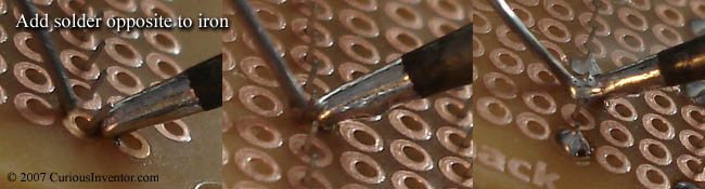
  • Apply solder to opposite side: Apply solder to the parts, not the iron. By doing this, you ensure the parts are hot enough for the solder to “wet” and bond with them. Also, solder will run towards the heat source, so applying solder opposite from the iron helps to spread it out and cover the joint.

    For larger joints, rather than dumping in all the solder quickly, continuously pulse in small amounts to keep a fresh supply of active flux available.

    Add solder opposite to iron

  • Time: The joint should take about 2-5 seconds total time for standard 60/40, 63/37 lead based solder and a non- no-clean flux, and up to 7 seconds for lead-free solder. Lead-free solder just takes longer to “wet” the metal.


    In general, the goal is to make the joint as quickly as possible. Longer times can char and damage the board, lift pads, overheat components, burn off and polymerize flux (making it harder to remove), and finally lead to a more brittle joint. Solder doesn’t just freeze on a joint, tin in the solder dissolves and chemically reacts with copper in the connection to form a new bonding material, called an “intermetallic layer”. While this layer is what makes an excellent thermal and electrical bond, it is also extremely brittle; a doubling of its thickness reduces joint tensile strength by half (ref 1). Since this layer grows faster with higher temperatures, joints should be made using the coolest temperature and shortest soldering time possible. This layer is also why re-heating joints has been shown to weaken them. Having said all this, I have to admit that I don’t know just how long is too long for projects that don’t need to operate for 30 years with 100% reliability. After 10 seconds there’s a good chance the flux has been used up.

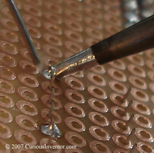
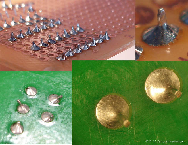
  • Remove solder, then iron: Pull the iron out fairly quickly to avoid leaving a solder spike.

    Remove solder, then iron

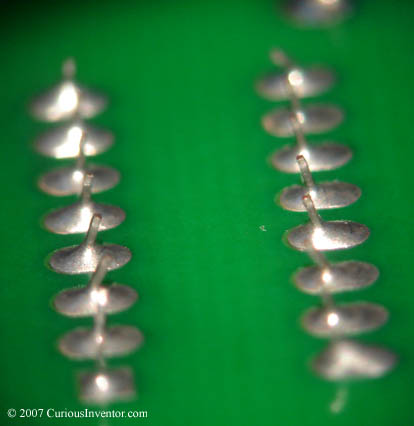
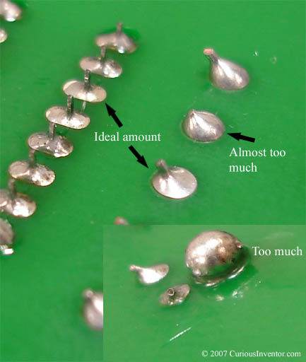
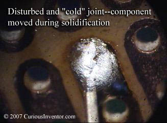
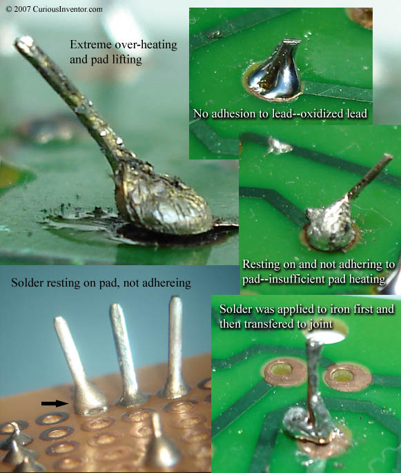
  • Good and bad joint gallery:The solder should smoothly ramp to meet surfaces and be shiny in appearance if it’s lead-based. Lead-free solder will have a duller and grainier surface, but will still be a good joint as long as there are no signs of non-wetting. The important thing to look for is any solder that looks like it didn’t cling to a surface, or is just sitting on top or next to a surface.Gallery of joints:

    A NASA gallery of every possible joint / board defect you could ever imagine. Here’s another great gallery of defects.

    Great comparison pictures between lead-based and lead-free joints. p. 34

Clean and tin the Tip

Oxidized tip

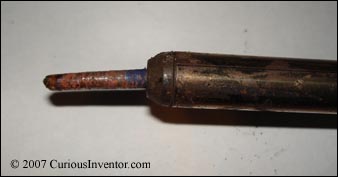
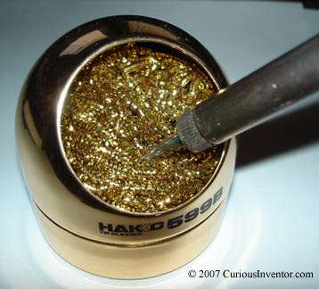
  • Regular cleaning = easier soldering and longer tip life:The iron tip’s ability to transfer heat is drastically reduced when it gets covered in oxides and burnt flux residues. Not only does heat not transfer as well through this debris, but the contaminants also prevent solder from wetting or sticking to the tip. Most heat transfer actually goes through a fluid solder “heat bridge” that lies between the iron tip and components, so an iron tip that repels solder will be very ineffective.The longer oxides and charcoaled flux residues remain on the tip, the harder they become to remove, so it’s a good idea to clean the tip every time you pick up the iron.damp sponge with hole Wiping the iron on an edge of a hole cut into a sponge can help to remove oxides easier, and also allows waste to fall away. A dry cleaner can also be used. It consists of soft metal shavings that are coated with flux. You clean by thrusting the iron into the shaving a few times. By avoiding the thermal shock of touching a damp sponge, these cleaners help to increase tip life, and in our opinion, do a better, faster job.

    cleaning with dry gold curls

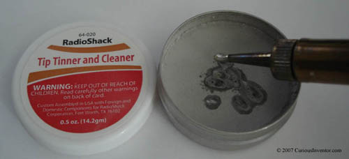
    Usually touching the tip with rosin-cored solder will supply enough flux so that oxides can be removed with a damp sponge. If this isn’t sufficient, you can purchase “tip tinners and cleaners” that are a mixture of solder paste and flux. The flux is oftentimes stronger (more activated) to help remove oxides.

    tip tinner/cleaner

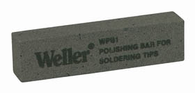
    Finally, when that doesn’t work, special polishing bars to can be used to salvage extremely bad tips. Another last resort is to gently rub the oxides off with an emery cloth or soft steel brush. Cover the tip immediately with solder after cleaning to prevent further oxidation. Never file the tip to clean it or form a different shape. The tips are mostly copper with a protective iron plating, and once that plating is pierced, the tip will die quickly. Copper is used because it’s an excellent heat conductor, but if exposed to solder, it will quickly dissolve into the solder.

    Weller polishing bar

    Tinning the tip

    Tin the tip: Add a small amount of solder back onto the tip. This helps to protect the newly cleaned and exposed tip, and also helps to transfer heat to components.

Prepare the Work

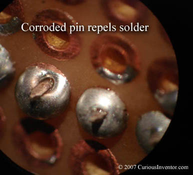
Corroded pin repels solder

    • Start with clean components: Flux can remove small amounts of oxides, but will be of little help for heavy oxidation, grease, oil or dirt. Notice how the solder in the adjacent picture has been repelled by the heavily oxidized pin. It may be necessary to lightly use steel wool or fine grit sand paper to remove especially bad oxides. Some people say that you should not do this because it creates scratches that can promote future oxidation… sand at your own risk. Use Silicon Carbide sandpaper (black) as opposed to Garnet (brown, for woodworking) sandpaper because the Garnet paper will shatter and become embedded in the metal. An effective and gentle alternative is to use a pink eraser, especially for copper traces.
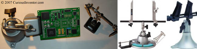
    • Clamp your work:PanaVise makes a popular clamp that accepts several different attachments for holding different sized circuit boards. It’s by far the most popular clamp and is also very sturdy. Having the work held in place is especially helpful for desoldering when it’s necessary to push or pull a bit. The alligator hands are a cheap alternative.
      Serveral types of clamps


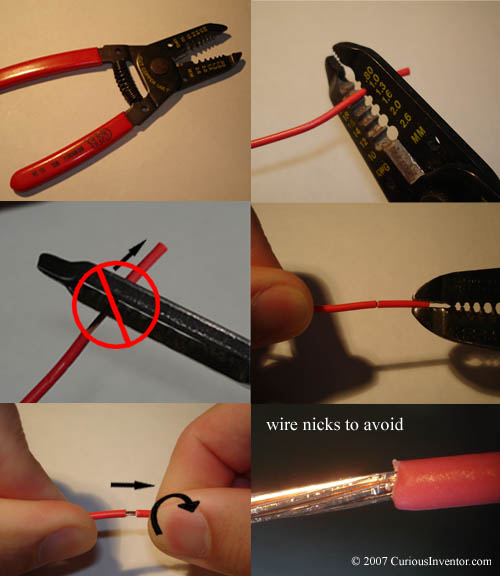
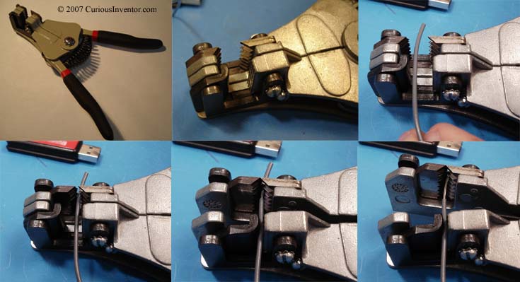
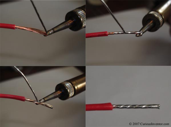
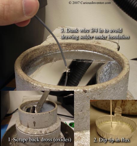
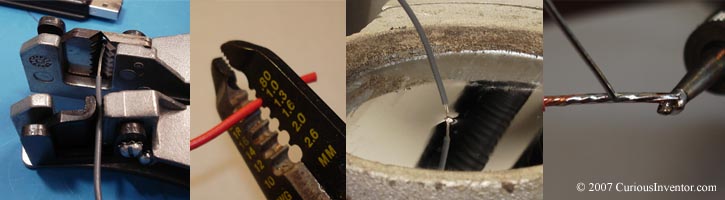
    • Wire preparation:Tin stranded wires so they don’t “bird-cage,” or bend out from their original lay. Expand for instructions on the correct way to strip a wire manually, use an automatic stripper, and tin wire. 


      Examples os tinning and stripping wire

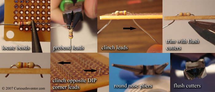
    • Insert, clinch and trim components: First, make bends beforeinserting the components. Avoid stressing the connection between lead and component by bracing the lead with pliers while bending. Pliers with serrated tips aren’t used in high-reliability production because the grooves can create nicks in the leads that eventually cause a break after a lot of vibration and thermal changes. Round nose pliers make it easy to make any sized radius.Unless the component has a metal casing or needs clearance for air flow to keep cool, insert it until it’s flush with the board. This doesn’t apply to some transistors, and also capacitors that have plastic coverings that need to be kept out of the solder joint. Clinch or bend out the leads so the component is held in place during soldering, and finally trim the leads to about the radius of the pad. Trim the leads before soldering since doing so afterwards can shock and crack the joint. Wearing safety glasses for this process is not at all excessive–those leads can get you. Everything else about proper component installation: NASA guide.

      Insert, clinch and trim leads


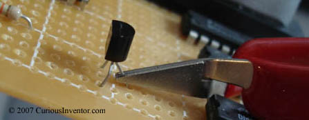
  • Add heat sink: Some semi-conductors (some transistors and diodes) are especially heat sensitive. This clip acts a heat shunt to keep the transistor protected.

    Heat sink on transistor

What kind of solder (rosin cored, etc. lead-free)? What is flux and when is it necessary?

As a starting place, for most small electronics soldering, 1/32 inch (.03) rosin-cored, 60/40 (tin-lead) or 63/37 solder should work fine. Rosin-cored lead-free is fine, too. Unless you have reason otherwise, don’t use “no-clean” solder–it’s very likely that you don’t need to clean the regular rosin-cored solder. The solder should be thin enough to prevent accidentally applying too much (and causing a solder bridge), but thick enough so that more doesn’t have to be gathered from the coil too often.

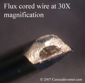
Flux core in wire-solder

Besides affecting your feed-rate and convenience, the solder thickness also relates to the amount of flux that is delivered. Flux is basically a weak acid that removes oxides so that solder can adhere to the metal, and is so essential to the soldering process that it’s built into the core of common wire-solder. It also helps the solder spread out (reduces surface tension), transfer heat, and acts as a protective blanket to keep oxygen away from the metal until solder displaces it.

For the most part, manufacturers include a sufficient amount of flux in the wire, but if you use an extremely thin wire there may not be enough to clean the joint OR the iron tip. Consider using a thicker gauge for cleaning the tip periodically if you’re using especially thin solder. Liquid flux is helpful for SMD soldering, too.

When picking a wire-solder, there are 4 features to decide on: flux type and amount (% weight), alloy (tin-lead, lead free, silver bearing, etc.), thickness and total amount (1oz, 1lb?).

  • Flux:Just what is flux, what kinds are there, and when do I need liquid flux?
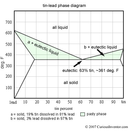
  • Alloy:60/40, 63/37, tin-lead, lead-free, silver bearing, RoHS, eutectic, oh my…
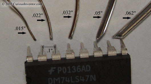
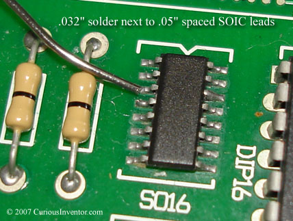
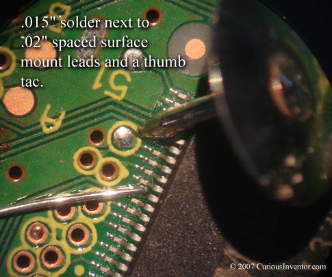
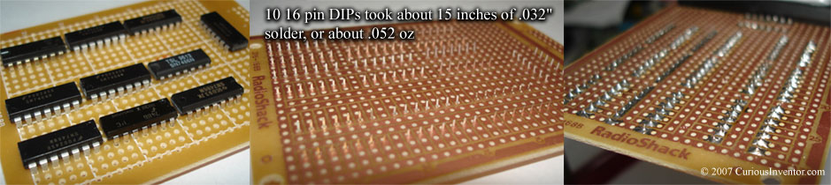
  • Thickness and Amount:As a general guide, .032″ thick solder (21 gauge) should be suitable for through hole soldering and some surface mount soldering. For finer pitch surface mount devices, use .02″ or .015″, and if you’re soldering a lot of switch terminals, or tinning thick gauge wire you may want .05″. If you use .015″ solder consider having some thicker solder on hand to re-tin your tip, since the amount of flux in .015″ may not be enough to remove tip oxides. The picture below shows how the various thicknesses compare next to the standard .1″ spaced DIP pins.Various solder thicknessesExpand to see how .032″ and .015″ solder compare to a SOIC surface mount chip and fine pitch (.02″) device.


    How much solder do I really need? An ounce? A pound? How long will a pound last?

  • Solder Fumes:What is exactly in solder fumes? Am I safer using lead-free solder?

Select a Soldering Iron

A 25 or 30 Watt iron should suffice for most small electronics work.


    1. Most soldering “guns” are vastly overpowered for electronics soldering and can easily overheat components or expose them to harmful voltages. However, some people cleverly use them to solder multiple leads on surface mount devices. Soldering “guns” are for plumbing and much heavier duty applications, and are usually over 100 Watts. The “guns” work by passing high currents through the tips, and these currents can generate voltages that damage electronic components. Also, magnetic fields from guns with transformers can damage some electronics.By forming the heating element in the shape of of the chip, a soldering gun can be used to heat many leads simultaneously.


    1. How much wattage do you need for a particular application and how does wattage relate to tip temperature?


A loose analogy: Imagine a car tire has a leak, but you’re trying to keep it inflated by pumping air into the tire at the same time it’s escaping out the leak. The bigger the leak, the more air you have to pump into it to keep the pressure up. If the tire pressure represents tip temperature and the air lost through the leak represents heat lost through the tip, then wattage represents the maximum amount of air your pump could supply. Once more air escapes through the leak than your pump can replace, the tire pressure (or tip temperature) starts to drop.


If you had a very small leak and a huge pump (say a 100 Watt iron equivalent), you might be afraid that the pump would cause the tire to explode since so much more air is going in and so little going out. But if you have a nozzle to regulate the pump’s air, you could only allow just the right amount of air in to replace what’s lost through the leak. This is how “temperature controlled” soldering irons work. As long as you aren’t losing more heat out of the tip than the iron can replace (up to its rated wattage), it will automatically regulate just the right amount of heat into the tip to maintain the same temperature.


However, typical plug-in irons have no such regulation. A 15 Watt iron always delivers 15 Watts of heat to the tip, and the tip temperature stops increasing only when 15 Watts of heat escape through the air. When the tip touches a part, its temperature drops, and if the part you’re soldering can dissipate enough heat, the temperature will keep dropping until it won’t melt solder any more. After the iron is pulled away from the joint, the temperature will climb again. There is some amount of natural regulation: as the tip gets hotter, it dissipates more heat, and as it gets cooler, it dissipates less.


Usually, the bigger the component the more heat it can absorb and dissipate, so the general rule is that you need more wattage for larger parts. If you’re just soldering small resistors and ICs, 15 Watts will probably suffice, but you may have to wait a bit in between joints for the tip to recover. If you’re soldering larger components, especially ones with heat sinks (like voltage regulators), or doing a lot of soldering, you’ll probably want a 25 or 30 Watt iron. For soldering larger things like 10 gauge copper wire, motor casings, or large heat sinks, you may need upwards of a 50 Watt iron or more. The following video shows what happens to tip temperature as 15, 25, and 40 Watt irons solder various sizes of wires and components. For cheap irons, higher wattage does indeed mean higher temperatures!


  1. What Watts, What? A short article about how much wattage is needed. From the article: “Power doesn’t do it. Temperature control does. All you need is enough power to keep the tip hot. Anything more than that is a waste.”


  • What is the difference between cheap RadioShack® irons and more expensive ones like Wellers®? What do $100+ and $400+ soldering “stations” have over the cheaper kinds that plug straight into the wall? expand Among the irons that plug straight into a wall and don’t have a separate station, the dirt cheap kinds will work satisfactorily for many applications. From personal experience, the tips on RadioShack® irons often come loose and sometimes can be impossible to remove. The irons can also get uncomfortably hot to hold after several hours of use. The more professional Weller (or other) lines are made for longer, continuous use and have insulation on the handles that keeps them cooler. They can also take a wider variety of tips.
    Soldering iron “stations” usually provide some control over the heat being supplied to the iron tip. Ones that are temperature controlled automatically control the amount of heat delivered to the tip so that it remains at a set temperature. In every iron, when the tip touches a component, some heat is lost and the temperature drops. One measure of quality is the time needed for the tip to regain its temperature. A nice feature of many soldering stations is that the tip heats up in seconds after you turn it on.
    Many stations also allow you to hot-swap the iron tip, which can be very helpful if you’re alternating between surface mount joints and larger components.
  • If standard tin-lead solder melts below 400 °F (and lead free below 500 °F), why do most soldering irons have tip temperatures between 600 and 800 °F? Just what is the right soldering temperature? expand The basic reason that tips are so much hotter than solder’s melting point is because that difference helps to transfer heat faster to the joint. What is the “correct” temperature is a debatable topic, but a common rule of thumb is to start off at 600 °F and increase from there until acceptable results are achieved. Typical Kester (a solder manufacturer) datasheets recommend 600-700 °F for lead-based solder, and 700-800 °F for lead-free solder. “No-clean” or “low solids” fluxes will burn off before a joint can be made with higher temperatures, so low temperatures (below 700) may be essential for these fluxes.
    From Kester’s hand-soldering knowledge base: “When hand soldering with a rosin flux such as the Kester #44 or the # 285 the recommended iron tip temperature is 750°F. If you are soldering with a low residue no clean solder such as the #245or # 275 we recommend a tip temperature of 600-650°F.
    What are acceptable results? The goal is to heat up the parts enough so that solder will adhere to them and form a good bond. The higher the iron temperature, the faster it will heat up the parts, so why not set it extremely high to work faster?
    Besides the obvious increased risk of overheating components and the board, higher temperatures cause the iron tip to oxidize faster and can significantly reduce its life. Some claim a 10 °C rise reduces tip life by half (ref p.33). For occasional use, though, tip life may not be much of a factor, especially if the tip is kept covered with solder at all times.
  • Tip size and shape: a basic guide is to pick a tip that’s slightly smaller than the pad you’re soldering to. From there, you want a tip with a large thermal mass and short stroke (why?)  In most soldering irons, the tip is not actually the heater, but sits in between your work and the heater. You can think of it like a heat bucket that empties into your work and gets filled again by the heater. Typically touching a component empties heat out of the tip much faster than the iron can replace it, and if you have a small bucket (tip), the temperature will quickly drop to an ineffective level.
    Especially if you have a small wattage iron (15 Watts or less), the temperature will drop before you can heat up a larger part, or you’ll have to wait a bit in between joints for the tip temperature to recover. With a bigger bucket (tip), you can handle larger joints with smaller wattage, but eventually you’ll need to step up the wattage.
    The “stroke”, or length of the tip should be minimized to get the heater closer to the work; it takes some time for heat to transfer through the tip. This is balanced with the need to get into tight places where you need a longer tip.


  • What do common tip shapes look like and what applications are they best for?
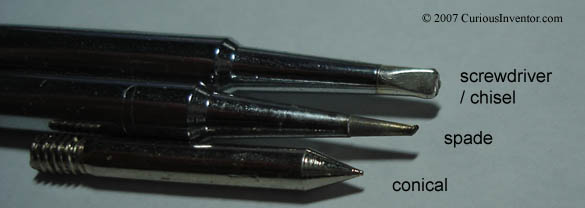
    three_tip_shapes.jpg
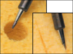
    Screwdriver, spade, and conical are some of the more common tip shapes. Personal preference is the biggest factor when choosing a tip, but the goal is to get as much surface area contact between the tip and work as possible. Chisel and spade tips have more surface area at their ends, and also “hold” solder at their tips more readily than conical tips, which have a tendency to draw solder away. Even for fine pitch surface mount soldering, having a small flat at the end can be helpful.
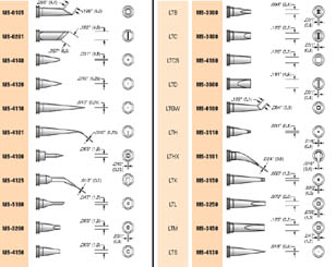
    plato_tip_catalog_page.jpg
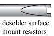
  • There are myriad other tip shapes and sizes. The picture to the right shows one Plato catalog page of many. Some other non-standard shapes include a knife-blade (useful for fine pitch leads) and a surface mount desoldering tip.desolder_surface_resistor.jpg

    knife_and_soic_tip.jpg
    desolder_soic.jpg

    To preserve tip life, the number one thing you can do is reduce the tip temperature (if your iron allows this). After that, ALWAYS keep a layer of solder on the tip to prevent the tip itself from oxidizing, and clean it in between uses. Put a glob of solder whenever you put it back in the stand, and before you turn it off. When heating up a new tip for the first time, hold solder against it so the tip can be covered as soon as the iron gets hot enough.
    The longer flux residues and oxides are left on the tip, the harder they are to clean off. They also can drastically reduce the tip’s ability to heat up a part, and prevent solder from “wetting” the tip. Regular cleaning of the tip before use is one of the best ways to prolong tip life and make soldering easier. It’s important that solder “wet” or cling to the surface of the iron–without solder in between the tip and work the tip’s ability to heat is drastically reduced.

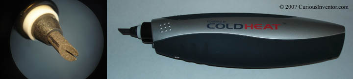
  • What about gas powered irons and the Cold Heat® iron that is supposedly touchable 1 sec. after use?  Butane (and other gas) powered irons are mainly used in situations where electrical power isn’t available. Weller sells some battery powered irons as well.
    Everyday Practical Electronics gives a pretty damning review of the Cold Heat iron here, in addition to having one of the better how-to guides out there. To summarize, the Cold Heat® iron has a forked end that you must bridge with the work or solder to turn on the iron, so it can be hard to hold it in a place that keeps it on and also effectively heats the part. Many people complain about pushing harder to make a good connection and then having the brittle tips break. Running power through your work to heat it may not be the greatest idea with some parts. Finally, the iron doesn’t get hot enough for a lot of jobs, or cool enough to do anything like throwing it in your pocket right after use. But for something that’s portable and cordless, heats up and down in under a few seconds, maybe it’s worth the price ($20).
    Weller’s battery powered ($20) iron doesn’t have a forked end and supposedly heats up in under 15 seconds, but I don’t know about cool-down time.


Cold Heat Iron

Interfacing a PS2 (PlayStation 2) Controller

Intro: There are all sorts of guides that explain how to interface a PS2 controller already out there. The goal here is to consolidate the information and make it as fast as possible to get up and running. Please let us know about mistakes!

Update: Check out the arduino ps2 library that Bill Porter helped polish.

Contents:


Hardware Interface / Wiring Connections:
playstation ps2 wiring connections interface protocol

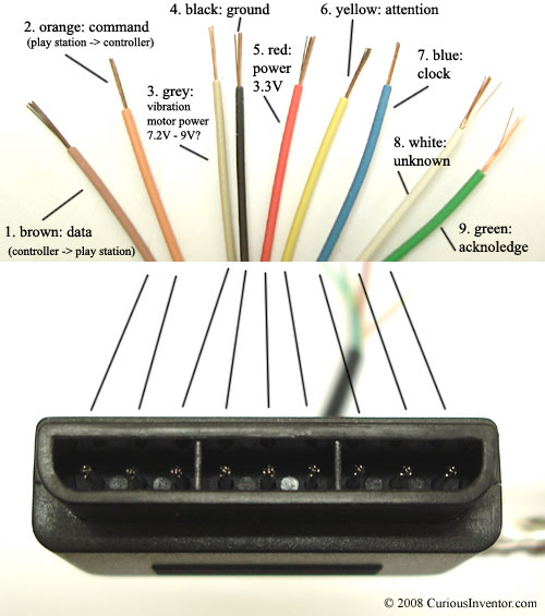
Wire Colors and Functionality: There are 9 wires, 6 wires are needed at a minimum to talk to the controller: (clock, data, command, power & ground, attention). To operate vibration motors, motor_power is also needed.

  1. Brown – Data: Controller -> PlayStation. This is an open collector output and requires a pull-up resistor (1 to 10k, maybe more). (A pull-up resistor is needed because the controller can only connect this line to ground; it can’t actually put voltage on the line).
  2. Orange – Command: PlayStation -> Controller.
  3. Grey – Vibration Motors Power: 6-9V? With no controller connected, this meausures about 7.9V, with a controller, 7.6V, most websites say this is 9V (except playstation.txt -> 7.6V), although it will still drive the motors down around 4V, although somewhat slower. When the motors are first engaged, almost 500mA is drawn on this line, and at steady state full power, ~300mA is drawn.
  4. Black – Ground
  5. Red – Power: Many sites label this as 5V, and while this may be true for Play Station 1 controllers, we found several wireless brands that would only work at 3.3V. Every controller tested worked at 3.3V, and the actual voltage measured on a live Playstation talking to a controller was 3.4V. McCubbin says that any official Sony controller should work from 3-5V. Most sites say there is a 750mA fuse for both controllers and memory cards, although this may only apply to PS1’s since 4 dual shock controllers could exceed that easily.
  6. Yellow – Attention: This line must be pulled low before each group of bytes is sent / received, and then set high again afterwards. In our testing, it wasn’t sufficient to tie this permanently low–it had to be driven down and up around each set. Digitan considers this a “Chip Select” or “Slave Select” line that is used to address different controllers on the same bus.
  7. Blue – Clock: 500kH/z, normally high on. The communication appears to be SPI bus. We’ve gotten it to work from less than 100kHz up through 500kHz (500k bits / second, not counting delays between bytes and packets). When the guitar hero controller is connected, the clock rate is 250kHz, which is also the rate the playstation 1 uses.
  8. White – Unknown
  9. Green – Acknowledge: This normally high line drops low about 12us after each byte for half a clock cycle, but not after the last bit in a set. This is a open collector output and requires a pull-up resistor (1 to 10k, maybe more). playstation.txt says that the playstation will consider the controller missing if the ack signal (> 2us) doesn’t come within 100us.

Low-Level – How Bytes and Packets are Transferred:

The play station sends a byte at the same time as it receives one (full duplex) via serial communication. The following pictures show actual signals between a playstation and guitar hero controller configured in analog mode (wammy bar sends back 7-bit value (0x7f – 0x00)).
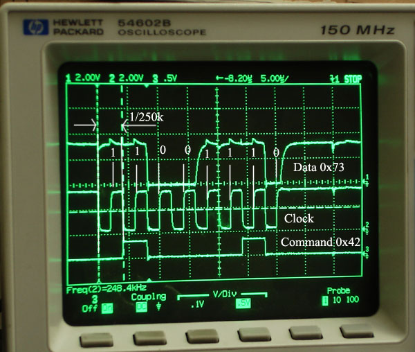
play station controller communication signals on scope

The clock is held high until a byte is to be sent. It then drops low (active low) to start 8 cylces during which data is simultaneously sent and received. When the clock edge drops low, the values on the line start to change. When the clock goes from low to high, value are actually read. Bytes are transferred LSB (least significant bit) first, so the bits on the left (earlier in time) are less significant.

playstation acknowldge, command, data, and clock playstation attention, command, data, and clock

Scope shots showing the acknowledge and attention lines.

High-level: Packet structure, Command and Data Meanings:

Much of this section is sourced from Dowty’s consolidation and home-brew port sniffer and emulator.

Packets have a three byte header followed by an additional 2, 6 or 18 bytes of additional command and controller data (like button states, vibration motor commands, button pressures, etc.).


An example exchange that from a dual shock controller when first plugged in:

Controller defaults to digital mode and only transmits the on / off status of the buttons in the 4th and 5th byte. No joystick data, pressure or vibration control capabilities.


(no buttons pressed)

byte # 1 2 3 4 5
Command 0x01 0x42 0x00 0x00 0x00
Data 0xFF 0x41 0x5A 0xFF 0xFF

Explanation:

— Header: (always the first three bytes)


byte # source /
type
example
value
explanation
1st byte Command 0x01 New packets always start with 0x01 … 0x81 for memory card?
Data 0xFF always 0xFF
2nd byte Command 0x42 Main command: can either poll controller or configure it.
See below for command listing
Data 0x41 Device Mode: the high nibble (4) indicates the mode (0x4 is digital, 0x7 is analog, 0xF config / escape?),
(lynxmotion calls 0xF ‘DS Native Mode’… not sure)
the lower nibble (1) is how many 16 bit words follow the header,
although the playstation doesn’t always wait for all these bytes
3rd byte Command 0x00 Always 0x00
Data 0x5A Always 0x5A, this value appears in several non-functional places

— Command / Mode Dependent Data (2 to 18 more bytes depending on mode):

4th byte Command 0x00 Can be configured to control either of the motors
Data 0xFF Each digital (on/off) button state is mapped to one of the bits in the 4th and 5th byte
5th byte Command 0x00 Can be configured to control either of the motors
Data 0xFF 1, or all 1’s (0xFF) means everything is unpressed.


Digital Button State Mapping (which bits of bytes 4 & 5 goes to which button):

button Select L3 (jush push) R3 Start Up Right Down Left L2 R2 L1 R1 Triangle O X Square
byte.bit 4.0 4.1 4.2 4.3 4.4 4.5 4.6 4.7 5.0 5.1 5.2 5.3 5.4 5.5 5.6 5.7

For example:

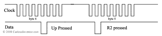
example play station clock and data signals when Up and R2 are pressed

Guitar Hero Button Mapping

button Green Red Yellow Blue Orange Up Down Select Start Wammy
byte.bit 5.1 5.5 5.4 5.6 5.7 4.4 4.6 4.0 4.3 byte 9: 0x7f (released) to 0x00 (pressed)
  • Bytes 4, 6, 7, 8 and 9 are normally 0x7F if nothing is pressed.

Command Listing / Examples:

The most comprehensive listings that we’ve found are Dowty’s and lynxmotion’s. This listing is based on information from both that has been tested.

— 0x41: Find out what buttons are included in poll responses.

The controller can be configured (through command 0x4F) to respond with more or less information about each button with each poll. Only works when the controller is already in configuration mode (0xF3)… use Command 0x43 to enter / exit configuration mode.

byte # 1 2 3 4 5 6 7 8 9
Command 0x01 0x41 0x00 0x5A 0x5A 0x5A 0x5A 0x5A 0x5A
Data 0xFF 0x41 0x5A 0xFF 0xFF 0x03 0x00 0x00 0x5A
section header bits corresponding to buttons in response packet
  • 18 total bytes can be turned on or off, including the 2 digital state bytes and 16 analog bytes (pressures and joysticks).
  • 9.cmd and 9.dat are always 0x5a.
  • Data is all 0x00 if controller is in digital mode (0x41)
  • Command data is always 0x5A, although 0x00 yields the same result.

— 0x42: Main polling command

Depending on the controller’s configuration, this command can get all the digital and analog button states, as well as control the vibration motors.

byte # 1 2 3 4 5 6 7 8 9 10 11 12 13 14 15 16 17 18 19 20 21
Command (hex) 01 42 00 WW YY 00 00 00 00 00 00 00 00 00 00 00 00 00 00 00 00
Data (hex) FF 79 5A FF FF 7F 7F 7F 7F 00 00 00 00 00 00 00 00 00 00 00 00
section header digital analog joy button pressures (0xFF = fully pressed)
analog map RX RY LX LY R L U D Tri O X Sqr L1 R1 L2 R2
  • If mode (2.data) is 41, the packet only contains 5 bytes, if mode == 0x73, 9 bytes are returned.
  • WW and YY are used to control the motors (which does what depends on the config).

— 0x43: Enter / Exit Config Mode, also poll all button states, joysticks and pressures

This can poll the controller like 0x42, but if the first command byte is 1, it has the effect of entering config mode (0xF3), in which the packet response can be configured. If the current mode is 0x41, this command only needs to be 5 bytes long. Once in config / escape mode, 0x43 does not return button states anymore, but 0x42 still does (except for pressures). Also, all packets have will 6 bytes of command / data after the header.

byte # 1 2 3 4 5 6 7 8 9 10 11 12 13 14 15 16 17 18 19 20 21
Command (hex) 01 43 00 0x01 00 00 00 00 00 00 00 00 00 00 00 00 00 00 00 00 00
Data (hex) FF 79 5A FF FF 7F 7F 7F 7F 00 00 00 00 00 00 00 00 00 00 00 00
section header digital analog joy button pressures (0xFF = fully pressed)
analog map RX RY LX LY R L U D Tri O X Sqr L1 R1 L2 R2
  • 4.command = 0x01 enters config mode (or ‘escape’ mode at Dowty calls it)., 0x00 exits. If 0x00 and already out of config mode, it behaves just like 0x42, but without vibration motor control.

— 0x44: Switch modes between digital and analog

Only works after the controller is in config mode (0xF3).

byte # 1 2 3 4 5 6 7 8 9
Command (hex) 01 44 00 0x01 0x03 00 00 00 00
Data (hex) FF F3 5A 00 00 00 00 00 00
section header config parameters
  • Set analog mode: 4.command = 0x01, set digital mode: 4.command = 0x00
  • If 5.command is 0x03, the controller is locked, otherwise the user can change from analog to digital mode using the analog button on the controller. Note that if the controller is already setup to deliver pressure values, toggling the state with the controller button will revert the controller back into not sending pressures.
  • Some controllers have a watch-dog timer that reverts back into digital mode if a command is not received within a second or so.

— 0x45: Get more status info

Only works after the controller is in config mode (0xF3).

byte # 1 2 3 4 5 6 7 8 9
Command (hex) 01 45 00 5A 5A 5A 5A 5A 5A
Data (hex) FF F3 5A 03 02 01 02 01 00
section header config parameters
  • 4.data = 0x03 for dual shock controller, 0x01 for guitar hero
  • 6.data = 0x01 when LED is on, 0x00 when it’s off

— 0x46: Read an unknown constant value from controller

This command is always issued twice in a row, and appears to be retrieving a 10 byte constant of over those two calls. It is always called in a sequence of 0x46 0x46 0x47 0x4C 0x4C. Only works after the controller is in config mode (0xF3).

byte # 1 2 3 4 5 6 7 8 9
Command (hex) 01 46 00 00 5A 5A A 5A 5A
Data (hex) FF F3 5A 00 00 00 02 00 0A
section header config parameters

second pass

byte # 1 2 3 4 5 6 7 8 9
Command (hex) 01 46 00 01 5A 5A A 5A 5A
Data (hex) FF F3 5A 00 00 00 00 00 14
section header config parameters
  • 4.command appears to get the first half of the constant when it’s 0x00, and the 2nd half when it’s 0x01.
  • As shown above, the constant returned for a dual shock controller is: 00 00 02 00 0A    00 00 00 00 14
  • A Katana wireless controller and the guitar hero controller each returned this: 00 01 02 00 0A    00 01 01 01 14

— 0x47: Read an unknown constant value from controller

It is always called in a command sequence of 0x46 0x46 0x47 0x4C 0x4C. Only works after the controller is in config mode (0xF3).

byte # 1 2 3 4 5 6 7 8 9
Command (hex) 01 47 00 00 5A 5A A 5A 5A
Data (hex) FF F3 5A 00 00 02 00 00 00
section header config parameters
  • Dowty thinks the first byte is probably an offset like in 0x46 and 0x4C, which would leave 5 bytes of interest.
  • As shown above, the constant returned for a dual shock controller is: 00 02 00 00 00
  • guitar hero controller and Katana wireless: 00 02 00 01 00

— 0x4C: Read an unknown constant value from controller

This command is always issued twice in a row, and appears to be retrieving a 10 byte constant of over those two calls. It is always called in a command sequence of 0x46 0x46 0x47 0x4C 0x4C. Only works after the controller is in config mode (0xF3).

byte # 1 2 3 4 5 6 7 8 9
Command (hex) 01 4C 00 00 5A 5A A 5A 5A
Data (hex) FF F3 5A 00 00 00 04 00 00
section header config parameters

second pass

byte # 1 2 3 4 5 6 7 8 9
Command (hex) 01 4C 00 01 5A 5A A 5A 5A
Data (hex) FF F3 5A 00 00 00 06 00 00
section header config parameters
  • 4.command appears to get the first half of the constant when it’s 0x00, and the 2nd half when it’s 0x01.
  • As shown above, the constant returned for a dual shock controller is: 00 00 04 00 00    00 00 06 00 00
  • A Katana wireless controller and the guitar hero controller each returned this: 00 00 04 00 00    00 00 07 00 00

— 0x4D: Map bytes in the 0x42 command to actuate the vibration motors

Only works after the controller is in config mode (0xF3).

byte # 1 2 3 4 5 6 7 8 9
Command (hex) 01 4D 00 00 01 FF FF FF FF
Data (hex) FF F3 5A 00 01 FF FF FF FF
section header config parameters
  • 0x00 maps the corresponding byte in 0x42 to control the small motor. A 0xFF in the 0x42 command will turn it on, all other values turn it off.
  • 0x01 maps the corresponding byte in 0x42 to control the large motor. The power delivered to the large motor is then set from 0x00 to 0xFF in 0x42. 0x40 was the smallest value that would actually make the motor spin for us.
  • 0xFF disables, and is the default value when the controller is first connected. The data bytes just report the current mapping.
  • Things don’t always work if more than one command byte is mapped to a motor.

— 0x4F: Add or remove analog response bytes from the main polling command (0x42)

This could set up the controller to only reply with the L1 and R1 pressures for instance. Only works after the controller is in config mode (0xF3).

byte # 1 2 3 4 5 6 7 8 9
Command (hex) 01 4F 00 FF FF 03 00 00 00
Data (hex) FF F3 5A 00 00 00 00 00 5A
section header config parameters
  • Each of the 18 bits in FF FF 03 correspond to a response byte, starting with the digital states, then 4 analog joysticks, then 12 pressure bytes.
  • By default, the pressure values are not sent back, so this is the command that is necessary to enable them.

Byte Sequence to Configure Controller for Analog Mode + Button Pressure + Vibration Control

The following sequence will setup a controller to send back all available analog values, and also map the left and right motors to command bytes 4 and 5.

— 0x42 Poll once just for fun

byte # 1 2 3 4 5
Command (hex) 01 42 00 FF FF
Data (hex) FF 41 5A FF FF
section header digital

— 0x43 Go into configuration mode

byte # 1 2 3 4 5
Command (hex) 01 43 00 0x01 00
Data (hex) FF 41 5A FF FF
section header digital

— 0x44 Turn on analog mode

byte # 1 2 3 4 5 6 7 8 9
Command (hex) 01 44 00 0x01 0x03 00 00 00 00
Data (hex) FF F3 5A 00 00 00 00 00 00
section header config parameters

— 0x4D Setup motor command mapping

byte # 1 2 3 4 5 6 7 8 9
Command (hex) 01 4D 00 00 01 FF FF FF FF
Data (hex) FF F3 5A 00 01 FF FF FF FF
section header config parameters

— 0x4F Config controller to return all pressure values

byte # 1 2 3 4 5 6 7 8 9
Command (hex) 01 4F 00 FF FF 03 00 00 00
Data (hex) FF F3 5A 00 00 00 00 00 5A
section header config parameters

— 0x43 Exit config mode

byte # 1 2 3 4 5 6 7 8 9
Command (hex) 01 43 00 0x00 5A 5A 5A 5A 5A
Data (hex) FF F3 5A 00 00 00 00 00 00
section header config parameters

— 0x42 Example Poll (loop this)

byte # 1 2 3 4 5 6 7 8 9 10 11 12 13 14 15 16 17 18 19 20 21
Command (hex) 01 42 00 WW YY 00 00 00 00 00 00 00 00 00 00 00 00 00 00 00 00
Data (hex) FF 79 5A FF FF 7F 7F 7F 7F 00 00 00 00 00 00 00 00 00 00 00 00
section header digital analog joy button pressures (0xFF = fully pressed)
analog map RX RY LX LY R L U D Tri O X Sqr L1 R1 L2 R2

Hand-shaking (first communication) recordings between Play Station 2 and Various Controllers

This excel sheet lists both the commands and response data between a play station and various controllers when the controller is first plugged in. Includes guitar hero, dual shock, wire less katana and chinese knock-off (looks the same as the dual shock).

Both a guitar hero game and dirt-bike game (to get vibration motor control data) were used.

We used 2 PIC18f4550 to do the port sniffing, see below to download the code.


PIC18f4550 Code to Read a PlayStation 2 Dual Shock or Guitar Hero Controller

The first program will configure a controller in analog mode so that all the joysticks and button pressures can be read. It also sets up the Left pressure to controller the left vibration motor and the Right button pressure to toggle the smaller right vibration motor.

Each command and response packet is sent out a serial port at 57600 kbs.

ps2_commander_reader.zip

The second program can operate in two modes:

  • Continous SPI to Serial: Every SPI byte is sent out the serial port at 57600. Since the play station communicates at 512kbs, the code uses a circular buffer to capture SPI bytes until the playstation pauses between packets, at which time it sends out the data via serial.
  • Bulk Capture and Dump: Caputer about 650 bytes of data into buffers, then dump the entire batch out through serial. We used this code to capture the initial communication between a Play Station and controller when they first connect. There are probably about 100 cleaner ways to do this, but the PICs we had on hand only had one SPI port, so two PICs were used at the same time to capture both the command and data lines. One PIC would send back it’s recordings immediately, and the other would wait for a few seconds, during which time a switch was flipped to connect the PC’s serial to the 2nd PIC.

ps2_listener.zip

Connection Schematic:

note: avoid connecting the PIC’s SPI clock to a play station’s clock when the PIC is configured as a SPI master.
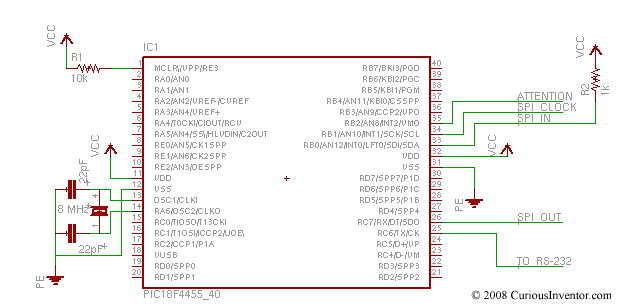

 

schematic ps2 to PIC18f4550

Making New Components and Modules (Footprints) in KiCad

NOTE: This tutorial was written in 1847, and kicad has changed a lot since then!

Intro:

This won’t go into every detail, but it will cover the unintuitive aspects of creating new components, including how the libraries work.

About the Libraries:

Unlike Eagle, where there is one type of library that contains both the schematic symbol and the footprint variations, in KiCad, .lib files contain schematic symbols and .mod files contain footprints, or “modules.” Cvpcb is used to map footprints to symbols.

Both of these libraries can contain from one to many parts.

LibEdit: Making New Schematic Components:

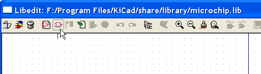
To create a new component, first launch LibEdit.

The most common approach is to modify a component from another library, and then save it in your own custom library.


First, open a source library. Here we choose the microchip library:


Then, load a component that you are going to modify, the 18F2550 PIC.

Let’s change the chip’s name by modifying its properties.

Select the “Fields” tab and click “Value/Chip Name”.

We’re going to call the new chip “magic_smoker”.

You now have a couple different choices for where to save this newly named part:

  • Save it in the current library: First save it in “ram,” and then to the hard disk. Saving in “ram” lets you update the symbol in the current schematic so you can see if the graphics fit within other components, for instance. If you don’t like the changes, just re-load the part from the source library as before since it hasn’t been changed on disk. Save to “disk” to permanently store the changes within the microchip library.
  • Save it to a New library: Clicking the new library button will open a dialog that lets you name a new library and save this part to it. Be aware that this new library and its part will not be loaded unless you update eeschema’s preferences to load that new library!!
  • Export the symbol: Export is the same as creating a new library, except that the default save location will be in your project directory, not the general KiCad library directory. Exporting simply creates a new library that happens to only have the one new part.

Creating a New Library in which to Save the New Chip:

Let’s take the 2nd option, and store the chip in a new custom library that will hold all of our custom schematic symbols.

We save the library as “curious_inventor_symbols.lib” inside the default KiCad library directory.

Two notes:
–The “current library” in LibEdit is still set to microchip.lib, not our new library. So if you were going to make more changes, be sure to switch to your new library before saving anything!
–We now need to update the preferences in Eeschema to load the new library, otherwise it won’t be able to load the chip. We do this next.

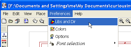
Close LibEdit, return to Eeschema and open the preferences.

Add the new library, and then be sure to save the configuration in the main .pro (project) file.

The manual does a good job of explaining how to make new parts. Our only advice is to avoid using the hidden power pins on new parts, and just keep everything visible and connected with wires. It can be especially confusing when you have multiple power levels.

Many of the same ideas apply to making new modules, but the library situation is slightly more confusing.

All about modules (footprints) and their libraries:

What files do I need to send someone else so they can load my schematic and board?

With schematics, they need to have the .lib files that contain the symbols, and those library files need to be loaded in the Eeschema preferences. On the other hand, with boards (.brd files), modules (footprints) can be stored inside the .brd file. You can send someone a .brd file and nothing else, and they would be able to look at and edit the board. However, when you want to load components from a netlist, the module libraries (.mod files) need to be present and loaded in the Pcbnew preferences just as with schematics. Also, it is necessary to load the .mod files in the preferences of Pcbnew in order for those modules to show up in Cvpcb.

If someone sends you a .brd file with modules you’d like to use in another board, you can open the module editor, load a module from the current board, and save or export it into another module library. You can also export all the modules in a .brd file at once via: Pcbnew–>File–>Archive Footprints–>Create footprint archive, which will create a new .mod file with all the board’s modules.

The Module (Footprint) Editor:


When you make a new component, it asks you for the reference. The reference is the name of the footprint.


<-Back  

About

CuriousInventor launched in late 2006 (pre-arduino era!) as a place to enable hobbyists, students, and musicians to create their own technology. We sold open-source kits and tools, and offered numerous guides & videos on things like soldering, metal working, screws, electronics, and more. 

The store is now mostly empty, but we’ve kept the product pages and guides up since they have useful information. Many of our guides and videos still rank on the first page of google searches and have been seen millions of times. Content on this site and the CuriousInventor YouTube channel produced by Scott Driscoll.

Top Videos