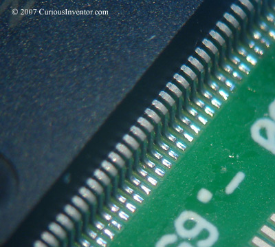
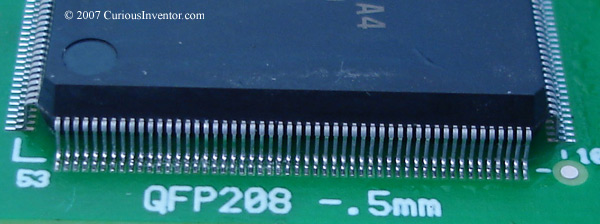
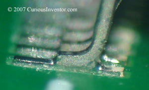
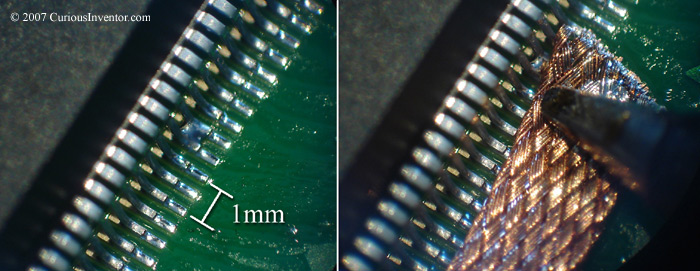
Experimentation with Solder Paste and a Toaster Oven

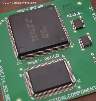
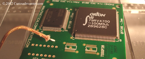
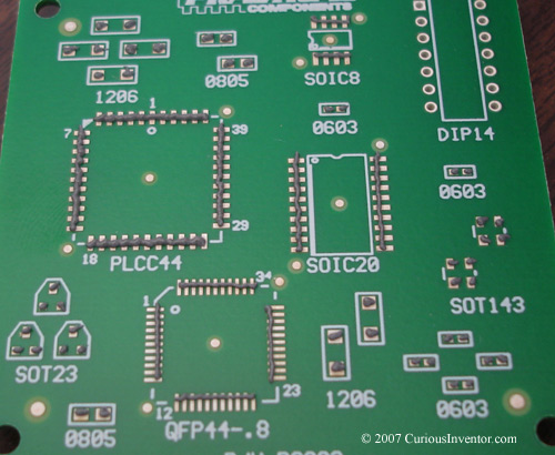
intro: This page will go over some of our first experimentation with solder paste and toaster ovens. Now, if you’re making several of the same board, the best route is to get a stencil and jar paste. Although slower, you can also apply paste with a syringe, and that is what we show in this guide. A double sided board with resistors, SOTs, QFPs, a PLCC and a fine pitch QFP will be soldered.

Equipment:

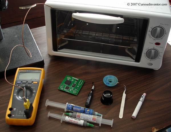
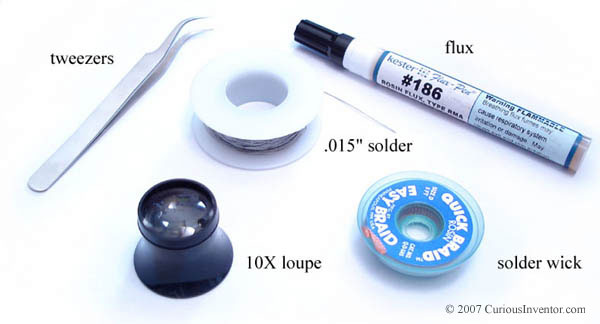
Basic equipment needed to use solder paste

Basic equipment needed to use solder paste.

essential equipment: Solder paste, tweezers, toaster oven, a loupe, microscope or magnifying glass for inspecting finished joints (you may not need this for larger pitches), solder wick for fixing solder bridges / shorts.


other things: temperature indicating crayon (watching the solder melt works, too), vacuum pickup tool for placing parts (tweezers and fingers will get the job done, too), thermocouple to measure temperature. A couple companies sell toaster oven controllers–some of which you can simply plug the toaster straight into. These are nice for being able to setup a temperature profile and log temperatures, but in our experience the ovens don’t heat up fast enough to require any throttling by a controller. They would probably be more useful for complex boards with many layers, large ground planes or ones with BGAs.

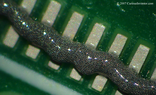
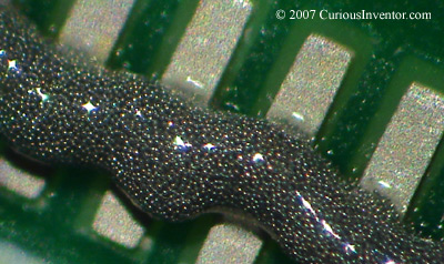
solder paste under 30X magnification

solder paste under 30X magnification

solder paste: Solder paste consists of small balls of solder floating within a gel-like flux. It’s an interesting animal that must be kept refrigerated to keep the flux from drying out. Also, the flux will slowly remove oxides from the metal–which is its job–but you don’t want it to get used up before the actual soldering operation; refrigeration also slows this process down. Some pastes have longer out-of-refrigeration shelf times than others, or may not require any at all–see the manufacturer’s recommendation.

Also note that the recommendations provided by manufacturers are geared towards industrial manufacturing with screen printing stencils and robotic dispensers. The industrial processes are designed to produce thousands of joints with minimal mistakes, so any small change in the paste rheology (how it acts under pressure) that causes an occasional defect would be unacceptable. But an occasional problem with a prototype can easily be touched up, so following the guidelines strictly may not be all that necessary.

Possible defects from dried out paste include slumping (the paste spreads out and causes bridges), solder balling, and clogging of stencils, which leads to insufficient solder coverage. Solder balling is when you find lots of tiny balls on your board that may come free and cause a short some day.

If you’re going to use a stencil, get paste in a jar instead of paste from a syringe. The syringe paste has slightly less metal to help it flow through a needle, whereas the jar paste is designed to work well with stencils. Many distributors will make you buy a plunger and needle to go along with the syringe. Digikey®, for instance, doesn’t even sell those, requires 2nd day shipping, and charges an obscene amount of money. There are lots of paste distributors; a little googling will save a lot of money. As for a needle size, I’ll recommend 22 gauge as a good starting place. You can control how much paste comes out by moving the needle over the pins faster or slower, too.

One last recommendation: get no-clean paste unless you have reason to believe your parts are very difficult to solder, and only then get water soluble paste. If you do use water soluble paste, the residues are conductive and corrosive, so be sure to clean them off with warm water.

The first side: including a 208 pin, .5mm pitch QFP

We’re going to attach components to both sides. The components on the first side will be held on by surface tension when the 2nd side bakes. Do the side with lighter components first to reduce the risk that any will fall off. PLCCs are rather heavy compared to the number of connections, so we’ll do the side without one first.

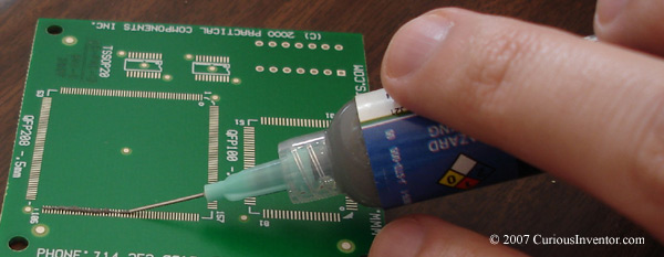
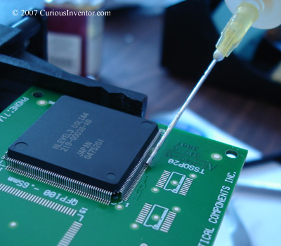
Applying solder paste to a fine pitch QFP

Applying solder paste to the pads of a fine pitch QFP

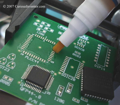
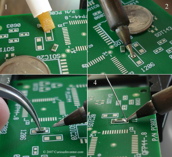
apply the solder paste: For fine pitch components, say .8mm and smaller pitch, just lay a bead of paste across the entire row. When it reflows, the paste will cling to the pads and connections and avoid bridging (for the most part). There’s a fine line between applying enough paste and adding so much that solder bridges are created. Some experimentation will probably be needed. For other components, place a small Hershey Kiss® of solder on each pad (see below for the 2nd side).

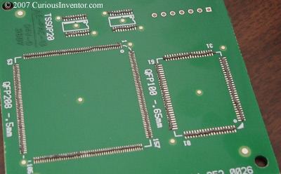
Solder paste a PCB

Solder paste a PCB

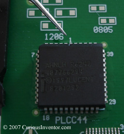
Components sitting on top of solder paste

Components sitting on top of solder paste

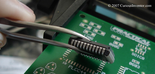
place chips on the paste: Using tweezers, fingers or a vacuum pickup tool, gently press components into the paste. If you smear the paste, wipe off the board area with alcohol and lint-free wipes and re-apply the paste. You want to avoid having bits of paste around the board since they will form into tiny balls that could come loose and cause a short.

Smaller components will snap into place when the paste melts, but larger components should be aligned as best as possible.

Baking the First Side:

the first side of a PCB with solder paste about to be baked

the first side of a PCB with solder paste about to be baked

what temperature and for how long? Paste and component manufacturers usually provide temperature profiles that give recommended and maximum values for the reflow process. If chips or boards are heated or cooled too fast, thermal stresses can break chips or warp boards. The paste will also not work correctly if heated too fast or too slow.

One question is just how critical the temperature recommendations really are. Most hobbyists or prototype builders aren’t trying to create 100,000 parts that last 5 years with no defects. But most industrial specifications are designed to provide that kind of performance. So, you might be able to get away with a lot of variation, but on the other hand, thermal damage may only show itself a week or month later–not on the first test. Also bad, the device might “sort-of” work, only producing bad results some of the time. So it’s probably best to follow the guidelines.

Reflow profile: As mentioned above, different components may have special requirements, but for a starting point, look at Kester’s standard reflow profile (this is for lead-based solder, they have a lead-free reflow profile, also).

There are 4 main zones:

  • preheat: The assembly temperature is raised to 100-150 degrees C with a max rise of about 2.5 to 3.0 degrees C/sec. The main purpose of this stage is to evaporate solvents from the paste and slowly raise the board and components’ temperatures to avoid thermal shock and warpage. Recommended time: 60-120 seconds.
  • soak: For a recommended time of 60-90 seconds, the assembly is slowly brought up to the solder melting (liquidus) temperature. This time allows the board temperatures to equalize and also for the flux to activate and clean off oxides from the metals.
  • reflow: This is where the solder is actually reflowed, or melted. A time of 60-150 seconds is recommend, along with a max temperature of 240 degrees C for lead-based solder and 260 degrees C for lead-free. During this time the temperature should reach peak and come back down again to the freezing (solidus) point. You don’t want to immediately cool off the assembly as soon as the solder melts; a little bit of time is needed to allow the solder to properly bond with the connections.
  • cool-down: To avoid thermal shock, keep the cool down rate below 6 degrees C / sec. Measuring board temperatures with a thermocouple, we found that everything cooled down much slower than this even with a wide open toaster oven door.

The above guidelines are based on an industry standard called IPC-J-STD-005 (not free). You can find the relevant portions of those specifications copied into this: PCB Land Pattern Design and Surface Mount Guidelines for QFN Packages. The Kester paste recommendations are slightly different. It’s probably best to start off with the lower temperature guidelines.

Again, all these parameters didn’t come into play since our toaster oven could barely heat up fast enough. We simply turned the toaster on full blast, waited for the solder to melt, counted to 15 and opened the door wide open. The board and components will have some impact on timing. Larger components will heat up slower, so be sure to make sure all the solder has melted before opening the door. If you’re using a thermocouple, place it next to the largest component. A chunk from a temperature indicating crayon will change colors permanently when its target temperature is reached. If used, place this by a large component, also.

Onto the 2nd Side:

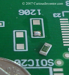
solder paste on a variety of component pads

solder paste on a variety of component pads

apply paste

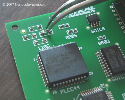
gently place components on the paste

gently place components on the paste

place components: Smaller components will self align during reflow, but larger ones should be carefully lined up.

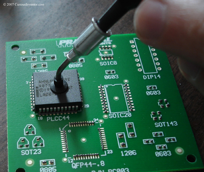
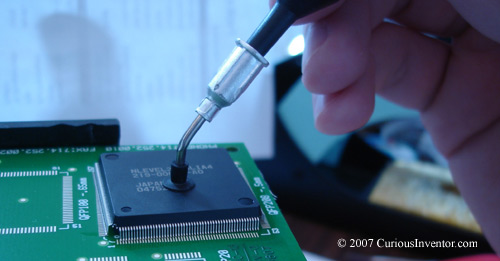
a vacuum pickup tool being used to place a PLCC

a vacuum pickup tool being used to place a PLCC

Bake the 2nd Side:

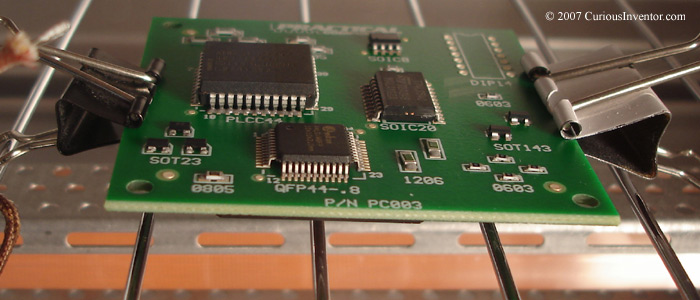
We used clips as stilts to hold the board up so the components already on the bottom wouldn’t touch the rack. We also tried using chunks of aluminum, but these drew too much heat away from the board, and the nearby joints didn’t reflow.

baking the 2nd side of a PCB with solder paste

baking the 2nd side of a PCB with solder paste

Results:

First, the bottom side components didn’t fall off.

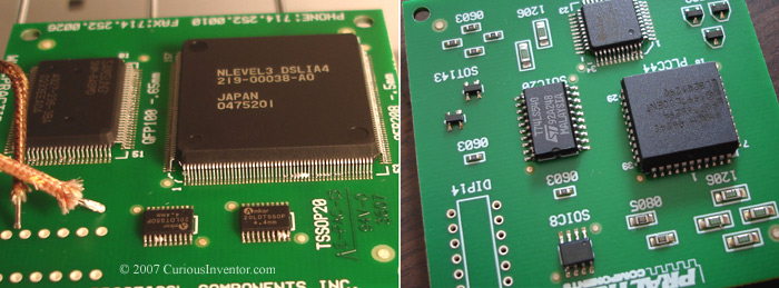
About 25 pins on our 208 pin, fine-pitch component bridged together. Besides a few other bridges, the other components turned out well.

Conclusion: If we had a stencil, this would be great, but hand soldering all these components may have taken less time than applying paste, placing components and then fixing bridges.

Both sides of a double sided board after reflowing in a toaster oven

Both sides of a double sided board after reflowing in a toaster oven

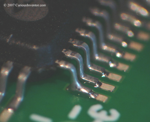
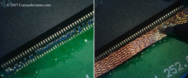
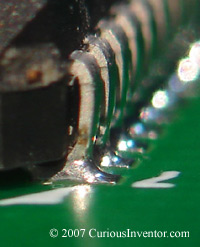
Up-close shot of one of the QFP leads showing a good joint.

Up-close shot of one of the QFP leads showing a good joint

References:

Other references and guides:

Soldering a QFN (Quad Flat No-Lead) Package by Hand

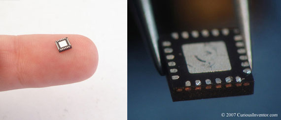
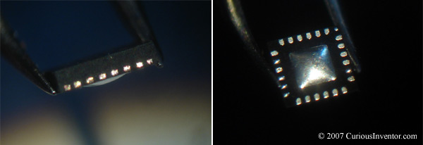
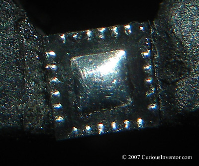
a QFN chip upside-down showing alignment markers on its side

an upside-down QFN chip showing alignment markers on its side

intro: QFNs are difficult because all the connections are on the bottom of the chip. Some versions have small extensions of these connections that wrap around the bottom corner and come up the edge a little. The perimeter connections (not the heat sink in the middle) on these can actually be soldered with a regular iron by applying lots of flux and touching each side and pad with a tinned iron. However, the version demonstrated in this guide only has small markers on the side, so hot air must be used to melt the bottom connections. Note that the best way to solder this chip is to use solder paste, a stencil and hot air (or a toaster oven or skillet), but we’ll be demonstrating a technique that doesn’t require either paste or a stencil.

New: Video Demonstrating Soldering a QFN using Hot Air without Solder Paste. 

The video also talks about air temperature and speed, and flux type.  The chip being soldered is a FM Radio from our Chipquik Lead Free SAC Solder Paste .


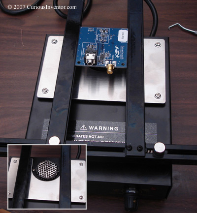
We’re going to show a hot air station ($250-$1000+) and an embossing tool ($25 arts and crafts tool for making raised ink decorations), as well as a hot-air pre-heater. You may be able to get by without a pre-heater, but it makes the job faster and less risky to the components and board. If you were doing a small one-sided board, you could also use a coffee cup heater, or, with a larger chip, a skillet set to about 100 degrees C.

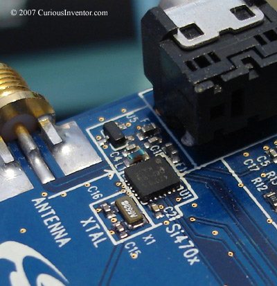
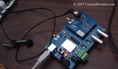
A 24 pin QFN from a SI Laboratories radio dev kit will be removed and then replaced.

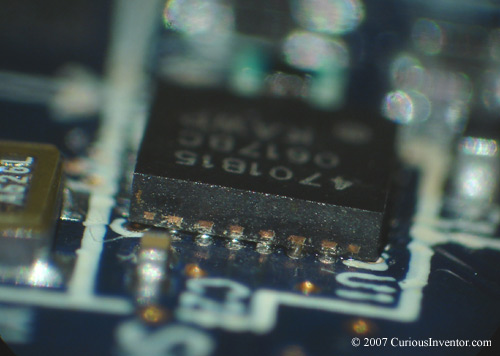
Original QFN Si4701 on a SiLabs Radio Dev Kit

Original QFN Si4701 on a SiLabs Radio Dev Kit

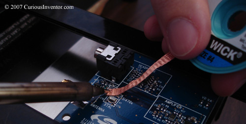
First, the original chip is removed by pre-heating the board and applying hot air using the same methods that will be detailed below. The pads on the removed chip and board are then cleaned by adding flux and using solder wick.

Using solder wick to clean the pads

Using solder wick to clean the pads

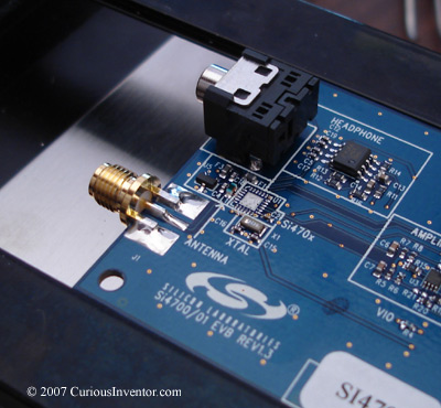
The PCB with QFN removed

The PCB with QFN removed

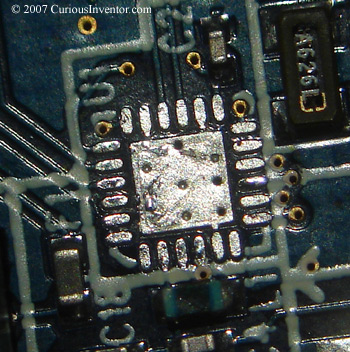
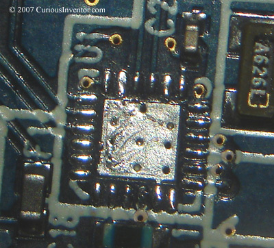
The cleaned QFN pads--note the vias in the heat sink pad

The cleaned QFN pads–note the vias in the heat sink pad


The heat sink has several vias (small holes meant to connect different layers on the board) that are used here to help draw heat away from the component and into the ground planes. While these help to keep the chip cool during use, they make it difficult to solder because heat from a hot air tool quickly dissipates into the board. A pre-heater is especially helpful if you’re going to solder the middle heat sink. However, many times it’s not necessary to solder this middle heat sink, and this is what makes soldering this chip especially challenging. So if you don’t need it, don’t add solder to it. And, if it’s your first time soldering a QFN, it’s probably best to skip the middle heat sink.

Adding flux to the bottom of a clean QFN chip

Adding flux to the bottom of a clean QFN chip

Before applying solder, clean off any old flux residues with alcohol and a brush, and then apply fresh flux.

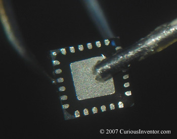
A small pillow of solder on the middle heat sink of a QFN

A small pillow of solder on the middle heat sink of a QFN

Apply solder to middle heat sink: To do this, tap a very lightly tinned tip against the fluxed pad until a small amount of solder wicks out onto the pad. The pillow of solder that forms should be very small, no more than 10 thousandths of an inch (1/3 of a 1/32″) tall. If you have calipers, you can check the pillow height by first measuring the original thickness and then comparing it the soldered thickness. If there’s too much solder on this pad, it will short to the outer connections during reflow. It’s better to have too little. Remove excess by applying flux and touching the solder pillow with a clean tip.

Tinning the outer connections of a QFN

Tinning the outer connections of a QFN

now tin the outer connections. Again, clean off old flux residue, add fresh flux, and touch a lightly tinned iron tip to the perimeter connections. Small beads of solder should collect on each pad. A microscope or loupe can be used to make sure each pad received solder.

QFN with center heat sink and outer connections tinned.

QFN with center heat sink and outer connections tinned.

Perimeter connections on the PCB tinned.

Perimeter connections on the PCB tinned.

tin the outer connections on the PCB: Do the same process for the PCB’s outer connections. Leave the middle heat sink free of solder.

Pre-heating the board

Pre-heating the board

Pre-heat the board: Turn the pre-heater on and wait a few minutes. If you have a thermocouple or other temperature display, you want the board to be about 212-250 degrees F before continuing.

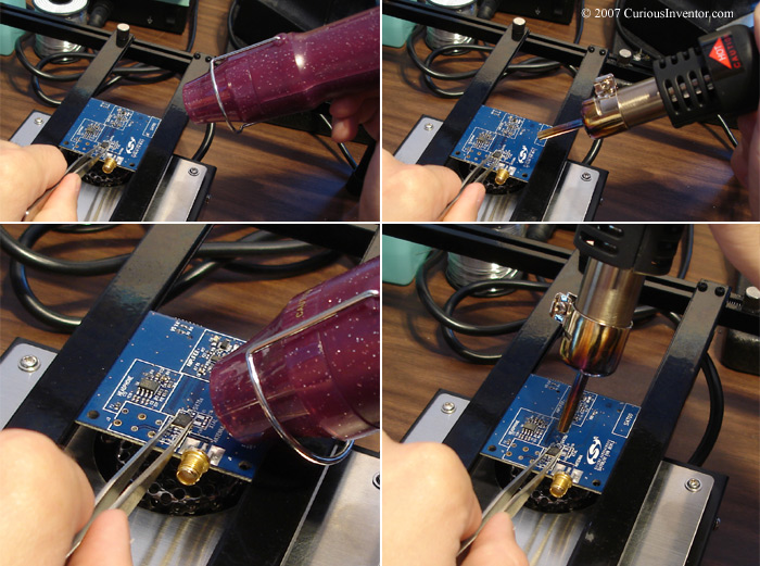
Using hot air from an embossing tool or hot air station

Using hot air from an embossing tool or hot air station


apply hot air: Holding the chip with tweezers, first apply hot air from a few inches away, and then move in to about 3/4″ away from the chip. Move the hot air in small circles. When the solder reflows, you should feel the chip drop into place. Let go with the tweezers. For this size of chip, surface tension will actually snap it perfectly into place unless there are shorts in the solder. Test to make sure it’s located by gently nudging the chip with tweezers–it should spring back into place.

Check to make sure alignment markers on the side are above the pads

Check to make sure alignment markers on the side are above the pads

Check to make sure the chip is lined up correctly: A loupe or microscope can be used to make sure the markers on the side are directly over their corresponding pads. You should also be able to barely see connections under the chip.

Still works!

Still works!

test your circuit: You can’t hear it, but our dev kit works once again with the re-soldered QFN chip.

Other references and guides:

Soldering a QFP and a Fine-Pitch QFP (.5mm)

(QFP: Quad Flat Pack)

The steps for soldering both of these chips are the same: add flux, tack some corners, add more flux and then solder the rest. We also use the same soldering iron tip for both–even the .5mm pitch. The leads on QFP’s are called gull wing leads.

Soldering a QFP:

The basic steps for soldering QFP

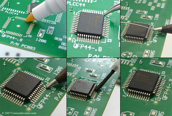
The basic steps for soldering a QFP chip with .8mm pitch.
    • flux the pads: This pre-fluxing will help hold the chip in place, and also ensures that the pads receive sufficient flux.
    • align the chip
    • add a small drop of solder to the end of a clean tip: This is the key to both tacking a corner and soldering the rest of the pins. You want a small drop of solder to hang off the end of the tip. Too much and you’ll create bridges or shorts between the pins.
    • tack two opposite corners: Gently slide the tip up against the toe of the corner pin. All you’re trying to do here is here is bring the solder drop in contact with the pin. Once they touch, surface tension will take over and wick the solder around the pin. This is the magic of surface mount soldering. Before tacking another corner, be sure to recheck the alignment and reheat the first pin if necessary. Once multiple pins are soldered, it’s almost impossible to make adjustments without completely removing the chip. Even with solder wick, surface tension will retain some amount of solder under the pin.
    • add more flux on top of the pins: You may want to do this before tacking the corners and skip the initial pad fluxing.
    • continue soldering the rest of the pins: Use the same technique to continue soldering pin-by-pin. With some practice, you can solder an entire row of pins at once by dragging a larger blob of solder over the toes–this is called drag soldering. Some of the tips that are specially designed for this technique are called “hoof” and “mini-wave” tips.

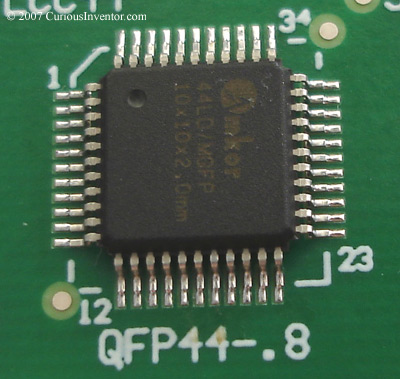
A finished QFP chip, loupe used to inspect the results, and up-close shot of an ideal joint.

A finished QFP chip, loupe used to inspect the results, and up-close shot of an ideal joint.


    • Industry specifications (IPC J-STD-001) indicate that there should be a fillet at the heel of the pin that smoothly connects the pad to the pin. So, you’re basically looking to make sure enough solder wicked around to the back of the pin, and that it looks like it adhered or clung to the metal. Lead-free and some fluxes for lead-based solder won’t look shiny, but this doesn’t necessarily mean the joint is bad.

A finished QFP chip

A finished QFP chip with flux residues cleaned off.

Soldering a Fine-Pitch QFP (.5mm Pitch):

We use the exact same steps to solder fine pitch components. For pitches down towards .5mm, using the loupe or some other magnification is more important for finding solder bridges or pins without enough solder.

Placing a 208 pin fine pitch QFP with a vacuum tool

Placing a 208 pin fine pitch QFP with a vacuum tool

First flux the pads, place the chip and align it with tweezers as usual. You’ll probably need to use the loupe to ensure the pins are centered on their pads. The picture shows a vacuum tool being used, but fingers and tweezers work, too–just be careful not to bend the pins. If you do, an Xacto® knife or a dental pic can be used to straighten them out again.

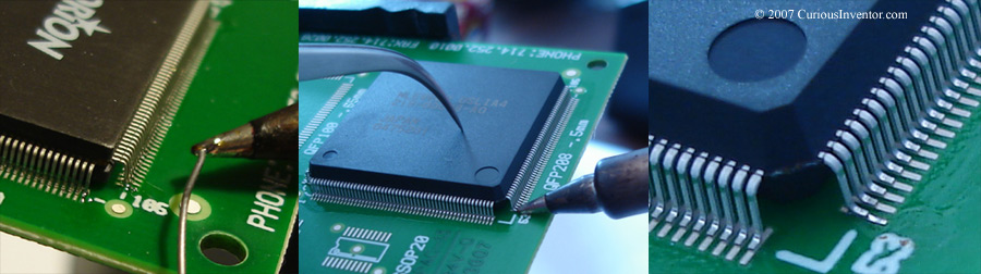
Tacking a corner pin.

Tacking a corner pin.

You’ll probably want to tack more than just two corner pins since two pins this small can easily be bent if the chip is bumped. Place a very small drop of solder at the end of a clean tip, and gently touch the toe of a corner pin. The right pane of the above picture shows just how little solder is needed.

Add more flux to the FPQFP pins

Add more flux

Add more flux on top of the pins.

Hand soldering the first side of a fine pitch QFP surface mount chip.

Hand soldering the first side of a fine pitch QFP

Continue soldering the other pins similarly. The pictures show just how close the soldering iron gets. Drag soldering can also be used, but it’s much harder to avoid creating bridges without a microscope on this pitch.

fpqfp completed joints

Completed fine pitch QFP joints.

Completed fine pitch QFP joints.

Completed fine pitch QFP joints.

Note how little solder is on each pin.

Magnified fine pitch QFP gull wing joint

Magnified fine pitch QFP gull wing joint

Again, the goal is to have a fillet at the back of the pin. Industry specifications state that the rear fillet should reach up to at least the height of the toe of the pin.

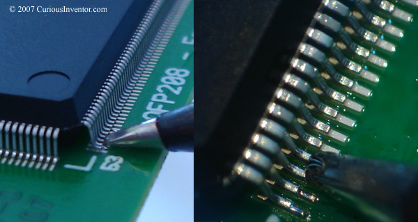
Removing a solder bridge on a fine pitch QFP with wick / braid

Removing a solder bridge on a fine pitch QFP with wick / braid

Solder bridges can be removed with solder wick / braid.

The Flood and Wick Method:

A very popular method is to flood the pins with solder, and then use wick to clear off all the bridges. This works because surface tension retains some amount of solder under the pin no matter how long the wick is applied. Industry folks don’t recommend this technique as it’s very easy to overheat the board or component. Also, solder wick has a tendency to freeze on pads or leads, and if you’re pulling on the wick when this happens, the pad or lead can easily be torn off. Finally, the wick can leave behind very little solder in the joint, which leaves the connection susceptible to breakage during vibration or temperature changes. If you use this method, be gentle and try to limit how long you apply heat to the part and board.

Flood and Wick method for surface mount soldering

The flood and wick method (not recommended).

Soldering a PLCC (Plastic Leaded Chip Carrier)

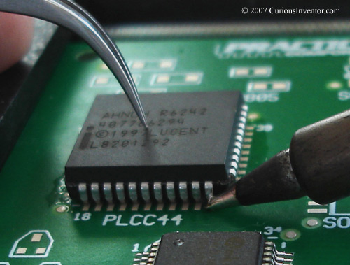
PLCC surface mount chip

The leads on a PLCC are called J-leads due to their shape. A brief summary of the steps is to flux the pads, tack two opposing corners, add more flux and then solder the rest of the pins.

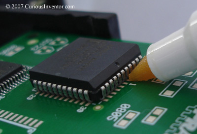
Fluxing the pads of a PLCC before placing the chip.

Fluxing the pads of a PLCC before placing the chip

First, flux the pads.

Align the PLCC on the board.

Aligning pin 1 of the PLCC on the PCB

Then align the part, keeping in mind that pin 1 on PLCCs is in the middle of a row, not a corner.

tacking one corner of a PLCC

tacking one corner of a PLCC

Place a small amount of solder on a clean tip, and then touch a corner pin and its pad while holding down the chip. You may want to add some flux to this pin beforehand. The next step is to tack an opposite corner, but be sure to re-check the alignment first. Once two pins are soldered you’ll need to completely remove the chip to make any adjustments.

Adding flux to the pins of a PLCC

Add flux to the pins of a PLCC

Add additional flux to the pins of the PLCC. The flux from the wire solder may be enough to skip this step, however.

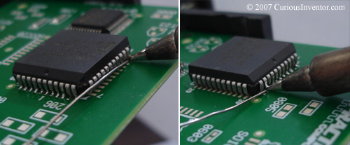
Soldering the first row of a PLCC

Soldering a row of a PLCC

Lay a piece of solder against the bottom of the leads and the board; .02″ diameter solder works well and is shown on the left. Now successively press the solder into each one of the pins. Heat each joint long enough to allow the solder to completely wick around to the back of the pin, but no longer.

Finished Results:

Soldered PLCC joints before the flux has been cleaned off.

Soldered PLCC joints before cleaning flux off

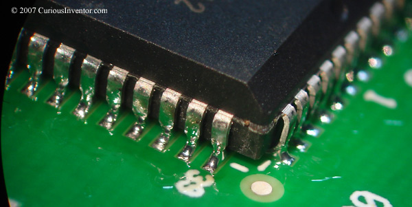
Ideal PLCC joint, flux cleaned off

Ideal PLCC joint, flux cleaned off

The goal is to have the solder wick all the way around to the back of the pin, and have a smooth filet (or curved ramp) connecting the pin to the pad in the front. The most important aspect is that the solder looks like it wetted (adhered to, clung to) the metal. Lead-free solder and some types of flux with lead-based solder will leave duller joints; this is OK.


Other references and guides:

Soldering Surface Mount Resistors

(and other small packages like capacitors, MELFs, DPAKs, SOTs, etc)

The basic steps for soldering most of these components are: add flux to the board, tack one pin of the component and then solder the other side. The picture below outlines these steps; more details follow below.

The basic steps for soldering surface mount chips (a 1206 resistor is shown): flux the board, tack the component and then solder the other side.

The basic steps for soldering surface mount chips: flux, tack, solder

A quick word about the packages: The resistive element is the colored side of a resistor, so it should face up to help dissipate heat. 1206 refers to the dimensions of its shape: 120 thousandths of an inch by 60 thousandths. 603’s are 60×30 thousandths and so on.

    1. add flux to the board: For larger components, like this 1206 resistor, you might not need flux if you melt flux cored solder directly on the pad. For smaller chips, however, oftentimes tinning the pad with wire solder will result in too much solder–a light touch with a tinned tip is all that’s required. In this case, extra flux is needed because no active flux would be left in the solder that’s on the tinned tip. Flux becomes active and quickly gets used up on the hot iron tip.
    2. add a small amount of solder to one pad: Again, very little solder is needed. Touching the pad with a tinned tip will provide all that’s needed for 603 and 402 sized chips. If you’re attaching a DPAK or SOT (small outline transistor), tin the largest pad (usually the heat sink) first. Tacking a smaller pin first will work, too, but you’re more likely to reheat all the pins when you heat up the larger heat sink later.
The first pad with solder added.

The first pad with solder added.

  1. tack one side:Using tweezers, lightly press down on the resistor and touch the junction between the chip and pad with a clean iron tip. You should feel the resistor drop into place. Ideally it would lay completely flat, but this isn’t an absolute requirement.

    One side of a 1206 resistor tacked

    One side of a 1206 resistor tacked
  2. add solder to the other side:Rotate the board and add a small amount of solder to the other side. To do this, hold the tip so that it touches both the component and pad, and then lightly touch it with solder. I like to add more flux to the 2nd side sometimes before this, but if you’re going to melt solder directly from the wire, it’s not necessary. For smaller packages, add a small drop of solder on the end of a clean iron tip first, and then touch the tip to the component and pad. This will help avoid adding to much solder.
    Adding a small drop of solder to the end of a clean tip

    Adding a small drop of solder to a clean tip.

  3. touch up the first side: If necessary, add more solder to the first side.
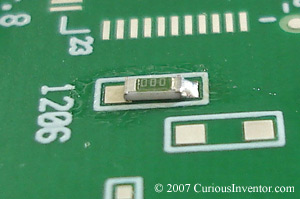
  4. finished result:The most important thing is that the solder looks like it adhered or clung to the metal. There should be a smooth fillet or ramp connecting the pad and resistor. A large blob of solder may work, but it’s hard to tell whether the blob is just sitting on the joint, or has actually bonded with the metal. The shininess of the joint is less critical. Lead-free solder won’t be shiny at all, and some types of flux in lead-bearing solder will result in duller joints that are still perfectly fine.
    An ideal 1206 solder joint

    An ideal 1206 solder joint.

These same steps can be used to solder just about any package with only a few pins.

Other references and guides:

Inexpensive Tools for Surface Mount Soldering

Intro: It’s not hard to spend thousands of dollars on surface mount soldering equipment. A good microscope and a hot air machine with nozzles for every different chip package will break the bank by themselves. Fortunately, it’s possible to solder just about every style of surface mount component without spending a fortune. This page covers our favorite inexpensive tools and supplies, starting with the essentials and then moving on to the more luxury items.

Bare Essentials:

Bare essential tools for surface mount soldering

  • flux: the key to surface mount soldering. Flux removes oxides from metal that prevent solder from bonding to it, and also helps to distribute heat. During typical soldering with flux-cored, solder wire, all the flux you need is contained in the solder. When the wire touches a hot connection, the flux flows out, cleans the joint and prevents further oxidation. However, in surface mount soldering, (brace yourself) oftentimes solder is melted on the iron, and then transferred to the joint. During this time, the flux quickly boils off and becomes useless, so additional flux is needed on the connection. If transferring solder in this manner seems questionable, bare in mind that a common process in industry, called wave soldering, is similar. Fluxed boards are slowly passed over a giant wave of molten solder that wicks into the connections.Flux comes in a large variety of different types and applicators. Our through-hole soldering guide goes over the different types, how the industry classifies them and whether or not cleaning the residues is necessary. To summarize, we recommend using a rosin-based, RMA (Rosin Mildly Activated) flux from Kester® (or anyone else that actually publishes specs on the corrosiveness of the residues). We don’t think cleaning of the residues is necessary for this type of flux for non-critical applications, but feel free to clean anyway–just be sure to do it soon after soldering because the residues quickly harden. “No-clean” fluxes have very low activation levels, and are therefore less effective than activated fluxes, but will work fine on clean parts. Use no-clean flux if you’re making circuits for NASA or are otherwise paranoid (And to feed the paranoia, note that many in industry clean no-clean fluxes). If you use water soluble flux, the residues are corrosive, and should be removed with warm water.


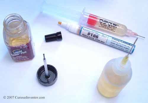
    Flux applicators: needle bottle, paste syringe, flux pen, and brush

    The above picture shows a couple means of applying the flux: bottles with needles or brushes, a flux pen and paste flux in a syringe. It’s easier to keep flux only where it’s needed with the flux pen than the needle or brush bottles. However, if you need to add more flux on top of fine pitch pins, the bottles are better since the pen could bend pins. The tackiness of paste flux is helpful for holding components in place.


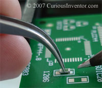
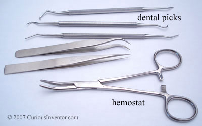
  • tweezers:Fine-tipped industrial tweezers are essential for handling the small components. Curved tips enable you to grab a chip from the top without having your hand directly above the chip. Hemostats are useful occasionally because they open wider than tweezers, and also lock closed. A set of dental picks or a Xacto® knife is also useful for nudging components and straightening bent leads.
    Curved tweezers holding a 1206 resistor Dental picks, tweezers and a hemostat

    1/2in Kapton High Temp Tape Roll

  • solder wick / braid: Used to remove bridges / shorts between pins. One popular technique is to flood the leads with solder and then wick up the excess, but this has risks associated with it–read our QFP surface mount side guide for more information. Soldering Iron Stand
  • solder: .015″ or .02″ diameter, flux-cored solder are sizes we prefer. We include 63/37 (63% tin, 37% lead) in our starter kit, but 60/40 works, too. A while ago, the circuit board manufacturing industry switched to 63/37 from 60/40 because it was more effective to some degree for mass soldering of surface mount chips. For the skinny on the differences between solders see the solder section from our through-hole soldering guide. In brief, 63/37 is eutectic, which means it freezes at single temperature (like water), whereas 60/40 goes through a “plastic” state where portions of it are frozen and others are still liquid. This means 63/37 freezes slightly faster, flows slightly better and is less likely to form a disturbed joint. Theory aside, we can’t tell much of a difference with hand soldering. Food for thought: water freezes at a single temperature, but a glass of water freezes from the outside in–not all instantaneously. 

    The major decision with flux-cored solder is which flux to use, and our above recommendations apply here, too: use a RMA or RA type and “no-clean” if you’re designing pace makers. And be sure to clean residues from water-soluble flux-cored solder.

    Some people recommend silver-bearing (containing) solder for SMD soldering. Solder containing 2% silver is available but was originally added to prevent solder from dissolving silver from sliver-plated components. While silver-bearing solder may be slightly stronger and have higher conductivity, these differences are extremely small and most likely insignificant.

  • magnification: With good lighting, you may be able to get by without any magnification for larger pitches (say > .8mm). A typical lighted magnifying glass on a boom arm is always helpful, but these only provide 2-3X magnification. 10X or more is useful when inspecting the smaller pitched components for sufficient solder and shorts between pins. A loupe is the cheapest route, but it can only be used for inspection after the soldering is complete. A stereo zoom microscope can be looked through during the soldering process, but these run $400+ used and much more for new scopes. Our scope recommendations are to get 30X magnification, stereo zoom, and the largest “working distance” possible. Working distance is the distance between the lenses and the work–the more room for tools and hands the better. Helping Hands


  • soldering iron and tip: A lot of this comes down to personal preference, but we recommend getting a temperature-controlled soldering station with at least 50 Watts, and a 1/32″ chisel or screwdriver shaped tip.
    • the iron / station:
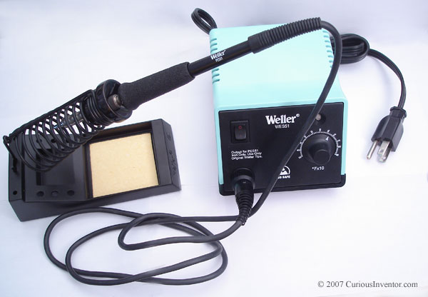
      our recommended soldering station: Weller WES51 (50 Watts, temperature controlled)

      our recommended soldering station: Weller WES51 (50 Watts, temperature controlled) or 4 Pos. Screw Terminal

      The small connections on surface mount components won’t draw that much power, so 15 Watts of power will work, but if you ever end up soldering to a large ground plane, big connector or a large wire, you’ll wish you had the power. Most hand-held irons are not temperature controlled, which means they’re constantly dumping out their rated power in heat regardless of the tip temperature. A temperature controlled station throttles the heat delivery to maintain a constant temperature. This is useful because the iron will push harder if you’re soldering a lot of joints or large components, whereas an unregulated iron will cool off and take longer to heat connections. Standard temperature recommendations are 600-700 degrees F for tin-lead solder, and 700-800 degree F for lead-free solder. Our surface mount video was shot using temperatures from 610-640 degrees F.

      On the topic of tip temperatures, here’s a youtube video showing tip temperatures of various RadioShack® irons while soldering.

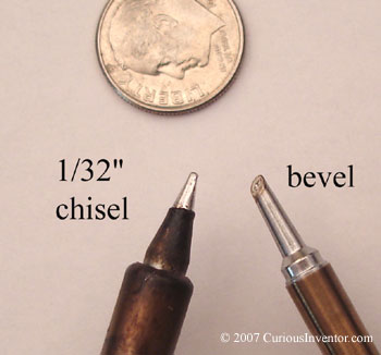
    • the tip: We use a 1/32″ chisel tip even on .5mm pitch components. Smaller tips won’t work with the techniques shown in our SMD soldering 101 video because it’s difficult to hold solder at the very end of the tip. The most popular technique for surface mount soldering, called “drag soldering,” uses an even larger tip to hold a blob of solder that can then be dragged over pins. Some names for drag soldering tips include “hoof,” “mini-wave” and “bevel” tips. We use the side of a chisel tip as shown in the video. Jumper Wire Kit (350 pieces)
      Chisel tip and bevel tip for surface mount soldering

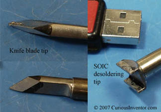
    There are also a variety of other tip shapes used for desoldering SMDs, but we don’t recommend buying a different tip for each chip–just use ChipQuik®, hot air or a skillet.

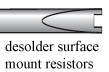
    Knife blad desoldering tip Desoldering tip for resistors

    A short video demonstrating desoldering a SOIC with a specialized desoldering tip.

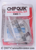
  • ChipQuik®:This is basically a low melting point solder that, when heated, stays molten long enough for all the pins to be released at once.
    ChipQuik SMD removal kit

    containing alloy, paste flux in a syringe, and alcohol pads for cleaning. Click the link for a 40 second demo video.


Hot Air: Essential for Soldering / Desoldering Leadless Packages

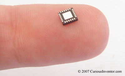
Some chips, such as QFNs (Quad Flat No-Lead), have connections on the bottom of the chip that can’t be soldered with a typical iron. Short of getting a SchmartBoard® or drilling a hole in the PCB, hot air is required to heat the connections (a skillet or toaster oven will work, too–see below).

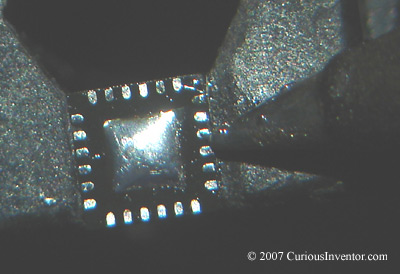
QFN (Quad Flat No-Lead) resting on a finger

QFN (Quad Flat No-Lead) package upside down showing the bottom connections around the perimeter and the heat sink in the middle.
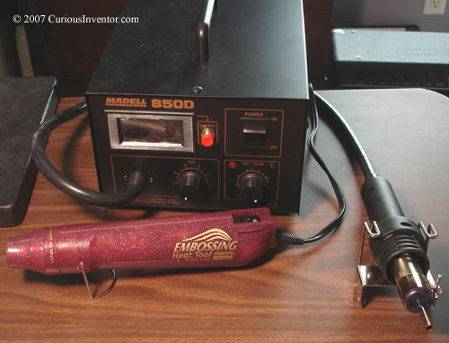
A hot air station and embossing tool

Hot air station from Madell and an embossing tool. We also recommend FM Radio Arduino Shield

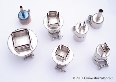
A wide assortment of tips that match just about every package style can be purchased, but we’ve had luck only using a 3/16″ round tip for all but the largest chips. The picture shows a relatively inexpensive hot air station that features both temperature and flow control. It also pictures something called an embossing tool that is normally used to create decorative, raised ink patterns on invitations and other arts & crafts projects. Conveniently, the air temperature is hot enough (low 600’s F) for surface mount soldering. The hot air station goes up to about 900 degrees F (going past 800 is risky), but for standard lead-based solder (lead-free requires slightly higher temps), the embossing tool gets the job done, and you can’t beat the price: $25. Note that standard heat guns from hardware stores have nozzles that are too large; they’re usually too hot, also.

Various hot air tips for soldering and desoldering

Various hot air tips
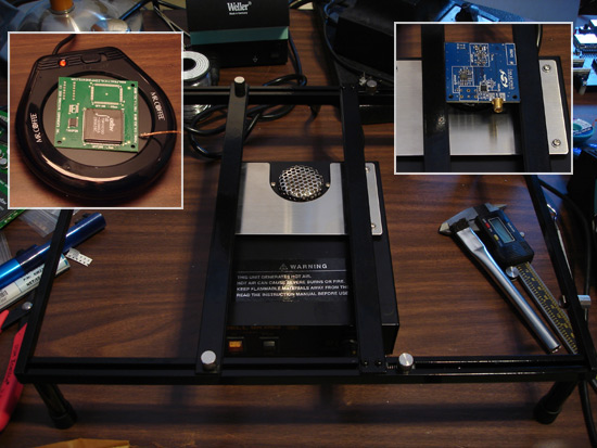
  • pre-heater / hot plate:For boards with larger components or ground places, much of the heat applied by a hot air tool gets drawn away from a target component into the surrounding board. This means more time and heat is needed to raise the target part up to reflow temperature, and this always increases risk of damage. Also, most components and solder pastes have limits on how fast they can rise in temperature. If one area of a chip or board gets hotter too much faster than another, thermal expansion can warp boards or destroy chips.Enter the pre-heater or hotplate. By raising the overall board temperature to 212-250 degrees F, less heat from the high temperature hot air tool will be required, and thermal shock will be much less severe. Madell and Zephyr sell fairly inexpensive pre-heaters, but a $7 Mr. Coffee® works well for small, single sided boards. You’ll need to get a PCB holder if you use one of the hot air pre-heaters.

    Can you get away without one? Probably, but be aware that thermal damage could reduce the life-span of your board, not simply kill it immediately. Preheating is even more important for BGAs, as their thermal profiles are much more critical.

PCB holder, pre-heater, and Mr. Coffee pre-heater

A PCB holder, pre-heater and a Mr. Coffee heater

The other route to go with leadless chips (or if you want to run small numbers of boards) is to use solder paste and a toaster oven or skillet.

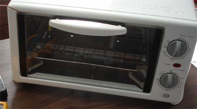
Small toaster ovens can be used to reflow solder paste

Small toaster ovens can be used to reflow solder paste
  • toaster oven:Ideally, a toaster oven is meant to recreate the temperature and time profile from a reflow oven in the real manufacturing process. This involves taking the board through a couple temperature stages where it’s first pre-heated, and then “reflowed” by raising the temperature above the solder’s melting point for about a minute. There are a couple companies out there that sell toaster oven controllers, namely ArticulationLLC.com and RheSiliconHorizon.com. These are neat because you can fine tune all sorts of parameters, and then just press “Start”. In our experience, however, small toaster ovens don’t heat up fast enough to require any sort of throttling by a controller. We simply turn it on high, wait for the solder to melt, and then open the door. A controller might be useful for more complex boards, though, and it’s nice to be able to log the temperatures.You want an oven that can go from 0 to 250�C (480�F) in less than 5 minutes in order to completely reflow the solder without baking the board. Our first purchase was a large, GE convection oven with 4 burners that took about 10 minutes to remelt solder (and burn the board). A $20, smaller oven with 2 burners did much better. So, if you get a large one, get the most wattage you can (preferably over 1400 Watts).

    As a later section in this guide show, you can do double sided boards in toaster ovens by propping up the PCB on stilts.

  • skillet: If you have a single sided board, a skillet can also be used to reflow solder paste. Try to get one that goes up to at least 450 degrees F. The guys at Sparkfun.com have some great tutorials / blogs about their surface mount soldering experience, and highly recommend using a skillet to reflow (melt the solder paste) their boards. They apparently had trouble dealing with a mix of plastic and large metal connectors in a real oven, but were successful with a skillet. One other advantage of a skillet is that you can easily remove chips with tweezers rather than trying to reach inside an oven.
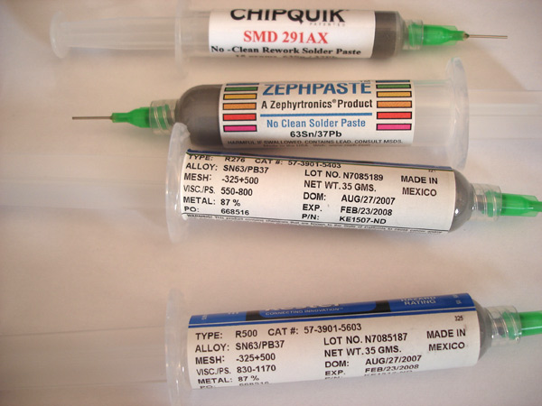
Several different brands of solder paste

Several different brands of solder paste


  • solder paste: This consists of tiny solder balls floating in gel-like flux. Once paste is applied to the pads, chips are placed on top, and the board is “reflowed” (paste melted) in a toaster oven or with hot air. Paste can be applied using the syringes shown or with a squeegee and stencil. For stencils, try StencilsUnlimited.com. Paste in syringes can be purchased from ChipQuik, Zephyrtronics, SMTSolderPaste.com and many others. Note that paste in syringes usually has slightly less metal content to help it flow through small needles. Get paste in a jar if you’re using a stencil. The main choice to make is between no-clean or water soluble paste. We recommend no-clean unless you have reason to believe your components are difficult to solder–ie, old and possibly corroded. The residues from water-soluble paste are corrosive, so be sure to clean them with warm water.Be aware that some distributors require 2nd day or faster shipping since paste lifespan decreases outside of refrigeration. If you get a syringe, you’ll likely have to buy a needle and plunger, too. A 22 gauge needle is a good starting place, and you can always lay a thicker bead of paste just by pushing more out.
Solder paste under 30X magnification

Solder paste under 30x magnification

Some non-essentials that are nice to have:

Various hot air tips for soldering and desoldering
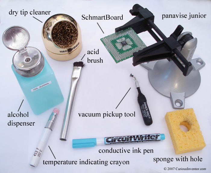
  • 4-40 Coarse Thread Tap and No. 43 Drill Bit : If you want to clean flux residues, use an acid brush with IPA alcohol. Be sure to wipe up the residues with a lint-free wipe (like Kim wipes) and not just move them around on the board.
  • Deburring Tool  Pushing down on the top pumps up a small amount of alcohol into the dish while keeping the rest from evaporating.
  • sponge with a hole: A whole in the middle gives you an edge to wipe the iron tip on, and also a place for the used solder to fall into so you’re not trying to clean the tip on older debris.
  • temperature indicating crayon: Marks from this permanently change color when it reaches a particular temperature, and is useful if you’re using a toaster oven without any thermocouples to watch the temperature. We had luck just watching for the solder to melt, though. In any case, different parts of the board will reach melting temperatures at different times due to ground planes and large components that suck up heat.
  • PanaVise Junior Clamp : An alternative to a sponge, it contains soft metal curls coated in flux that clean the tip without thermally shocking it. This can help to prolong tip life.
  • 10-24 Coarse Thread Tap : The smaller version of the popular PanaVise has slots to hold circuit boards, and is much more stable than “helping hands.”
  • Softpot Touch Sensors : This company makes a whole line of prototyping boards for surface mount components, including anything from resistors to fine-pitch QFPs to QFNs to BGAs. It’s a clever product that uses small troughs pre-filled with solder to align the chip. To solder, you simply push the solder up to each pin with a small iron tip.
  • fixing mistakes: The conductive ink pen lets you simply draw traces on a board. Another option is to use tiny wire (such as 30 gauge wire wrap wire) to jumper over mistakes or lifted pads. These are called “green wires” because manufacturers initially used green colored wire to blend in with the green PCB.
  • Plug-in Bread Board Dual Power Supply : (not shown) A tip tinner / cleaner (which you can still get from RadioShack®!) has a more aggressive flux in it that can help clean stubborn residues off a tip. You can also get a polishing bar to refresh a dirty tip. Polish lightly, though–once the protective outer plating is pierced solder will quickly dissolve the copper inside.

Other references and guides:

Surface Mount Soldering 101

9 min. overview video demonstrating Surface Mount Soldering with inexpensive equipment. Includes soldering of a 603 resistor, PLCC, 44 pin QFP, 208 pin fine-pitch QFP, desoldering using hot air and ChipQuik®, and prototyping with SchmartBoards®.

Surface Mount Soldering

Contents and Introduction:

Surface Mount components, as the name suggests, attach to the surface of boards, not through holes like older components. SMDs (“Surface Mount Devices”) are lighter, cheaper, smaller and can be placed closer together. These factors, among others, mean that the days are numbered for through-hole components with widely spaced leads.

This set of guides will demonstrate (relatively) inexpensive tools and methods for soldering and desoldering SMDs.

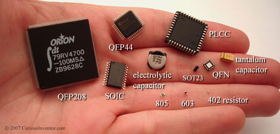
SMT Components QFN QFP 603 PLCC tantalum 402 SOIC


  • Video: Surface Mount Soldering 101 : A 9 min. video showing the basics of SMT soldering and desoldering without expensive equipment. Includes soldering of a 603 resistor, a PLCC, a 44 pin QFP and a fine-pitch, 208 pin QFP, as well as desoldering with ChipQuik®, and prototyping with SchmartBoards®.
  • Tools for Surface Mount Soldering : Pictures and descriptions of relatively inexpensive tools needed to solder anything from resistors, to fine-pitch QFPs, to leadless QFNs.
  • Soldering a 1206 Surface Mount Resistor: A tutorial on soldering a 1206 resistor. These techniques can also be used to solder other small devices, such as capacitors, MELFs, SOTs, DPAKs, etc.
  • Soldering a PLCC: A tutorial for soldering a PLCC (Plastic Leaded Chip Carrier). These steps will work for any package with J-leads, also.
  • Soldering two QFPs: a 44 Pin and a 208 Pin Fine Pitch QFP: A tutorial showing how to solder a .8mm QFP (Quad Flat Package) and a 208 pin, fine-pitch QFP.
  • Soldering a QFN (Leadless Package) by Hand(Now with video) QFN (Quad Flat No-Lead) Packages are tricky because the connections are actually on the bottom of the chip, including a heat sink in the very middle. This guide covers techniques for soldering these chips by hand without a stencil, paste or reflow oven. Relatively inexpensive equipment is used, also.
  • Paste and Toaster Oven Experimentation: This guide describes our first foray into using paste and toaster ovens to solder a double sided board with fine pitch components. We try out two types of ovens, review a toaster oven controller, and give a step-by-step process overview.

All about screws

This guide is written for hobbyists, prototype builders or engineers looking for some basic information and intuition like:

  • “How large of a screw/bolt do I need?”
  • “What types of screws are out there and what are the for?”
  • “What are washers for, and do lock-washers work?”
  • “How tight should a screw be, and how does that affect how much load it can handle?”
  • “Coarse vs. Fine thread?”

* If it really matters (risk to property or bodily harm), hire a professional engineer; there could be errors in this guide.

Contents

Terminology and basic identification

What’s the difference between a bolt and a screw? Most sources (like the Machinery’s Handbook) define screws and bolts in terms of how they are installed: if you turn the head it’s a screw, if you turn a nut it’s a bolt. A hex head cap screw and hex bolt may look identical. This guide refers to both interchangably.


Wood, Sheet Metal and Drywall Screws – differences, uses, and head types

  • Wood Screws: These have a coarser pitch (few threads per inch) than sheet metal or machine screws, and often have an unthreaded shank. The threadless shank allows the top piece of wood to be pulled flush against the under piece without getting caught on the threads. Some wood screws are tapered from tip to head, also. This site lists pre-drill sizes for various sized screws. Wood screws vs. sheet metal screws
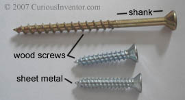
  • Sheet Metal Screws: Usually threaded all the way to their head, these will work in wood, but wood screws shouldn’t be used in metal (this is based on hardware store employee advice, not experimental evidence). Most of these screws are self-tapping in that they only require a pre-drilled hole (pre-drill sizes), but some come with self-drilling (shown in above pic) or self-tapping tips. Here’s a large list of different types of tips, the more common ones appear to be A, AB (pointed) and B (no point). Here’s a good guide to the different point types and uses. See more pics of thread cutting screws hereEven more good pictures of different head types. 2 Drywall and 1 self-drilling sheet metal screw
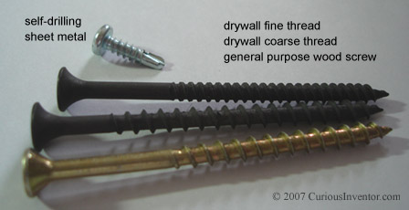
  • Drywall Screws: The coarse thread version is meant to secure drywall to wood while the fine thread version is for attachment to metal studs (commonly used in office construction). The head-to-shaft junction is more curved than in a wood screw to prevent tearing of the dry-wall. These can also come with self-drilling tips.

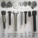
Common Head Types for the Above Screws (and 3 machine screws)
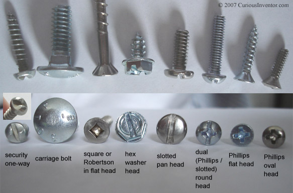

Screwheads commonly found on wood and sheet metal screws

  • Slotted, Phillips and Square drives: The main drawback of slotted heads is that power driven screw drivers easily cam out. Phillips heads address this problem to a certain extent, but these were actually designed to cause the bit to cam out at a certain point to prevent over-tightening. There have been revisions of the original Phillips head, most notably the patented Pozidriv, which does not have rounded internal corners and won’t cause the driving bit to pop out. The square or Robertson drive is least likely to cam out and transfers the greatest amount of torque. The wiki Screw page and this one describe some other less commong drives.
  • Round vs. Pan head: A pan head is successor to the round head, and is slightly flatter with greater thickness near its circumference than the round head. This supplies more surface area for the driving bit to grip over the round head, especially for slotted or flat drivers.
  • Carriage Bolts: These have a square shank that sinks into and grips wood when a nut is tightened.
  • Flat and Oval Head: The most common type of head for wood, these heads end up flush or below the surface of the wood when installed. An oval head is similar, except that it has a decorative rounded top that remains above the surface.
  • Security Heads (tamper proof): These screws have heads that are either impossible to reverse or require a special driver to operate. Some other types include the spanner (two small holes), tri-wing (used on the Wii), and torx or square drives with pins protruding up in the center of the socket. Some even have sacrificial heads that can be broken off after installing the screw. Here and here are several pictures of these screws.
  • Hex Washer Head and Truss head: These screws have a built in washer to help distribute load to a wider area. A truss head (not shown) is a flatter and wider than a typical round or pan head and serves the same purpose. These are commonly found on license plates.


This fastener guide gives a great pictorial overview of just about every fastener type, and here is a good overview of possible head types..

This talks about different screw types and their uses, also a bit about washers and rivets.

contents ^

Machine Screws

Machine screws are generally stronger than wood screws, have finer threads and are made more precisely. They’re used with nuts or tapped holes. Several examples are shown below. Several machine screws
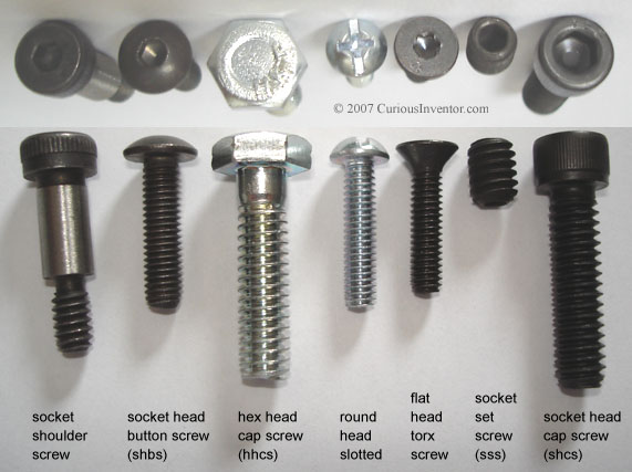
  • Socket Screws: While many hex cap screws may be found in vehicles, socket head screws are becoming more popular and have some space saving advantages over hex cap screws. Socket heads take up less space themselves and don’t require side room for wrenches. They also are usually made from stronger alloy steel vs. hex cap screws, but this depends on the grade and manufacturer.
  • Allen / Hex Socket vs Torx: Most socket head screws accept a hex or Allen wrench (6 sided), but Torx heads (loosely, a 6 pointed star) are also available. Torx sockets were originaly designed to prevent the driver from camming out, and can transfer more torque than a Phillips or slotted driver. They don’t require large amounts of pressure to keep the bit in the socket. Some people say that it’s faster to insert a bit into a Torx screw than a hex socket, which would be advantageous in manufacturing environments.
  • Button Head: This head is largely decorative and somewhat similar to a round head, but flatter.
  • Flat head (counter sunk): These require a pre-drilled counter sink, and are typically angled at 82 degrees (Unified thread), which, by the way, is not the angle created by most drill bits (118 degrees). Metric flat heads have 90 degree angles.
  • Shoulder Screws: These have precision ground shanks that remain above the head of a hole and provide a simple way to make an axel for a wheel. They are also used when something must be secured, but not clamped.
  • Set Screws: These are threaded along their entire length and are typically used to secure a shaft from rotating. They’re used in pulleys, sprockets, collars and knobs among other things.

Here’s a great doc from tessco that talks about different screw types and their applications, grade and strength information, and screw material guidance.

contents ^

Thread Types: Most common types and when to use which


The most common thread types are the inch-based Unified coarse / fine (UNC/UNF) and metric coarse / fine. Other types and their purposes are described at the end of this section.

Coarse or Fine? To oversimplify, use a coarse thread unless you’re tapping into sheet metal. The differences are:

  • Coarse theads have fewer threads per inch than fine threads.
  • Coarse threads are more common, and more shops will have coarse taps.
  • Coarse threads are less likely to cross-thread, or jam because the screw is inserted at an angle. They’re also faster to install.
  • Screws with fine threads are slightly stronger. This is because the smaller fine threads take up less of the available area. See the loading charts below to see typical differences between the tensile strength of a fine vs coarse thread. A 1/4 UNF thread is about 14% stronger than its UNC counterpart.
  • Coarse threads are slightly stronger (against stripping) per length of engagement than finer threads (see thread strength section below). This may be surprising given the almost universal recommendation that fine threads be used in sheet metal and other thin-walled materials. If coarse threads are stronger and there is less than optimal thread engagement length available, wouldn’t it better to use the stronger threads?
  • Coarse threads are more tolerant to slight damage or corrosion than fine threads since they have more room for error.
  • Fine threads provide finer adjustment since they advance less per rotation than coarse threads.
  • The metric coarse thread is actually between UN coarse and fine thread, and the metric fine thread is finer than the UNF threads. Blake’s “What Every Engineer Should Know About Threaded Fasteners: Materials and Design,” recommends not using fine metric threads.


Thread specification – How threads are notated / designated:

example Unified thread designation:

1/4-20 UNC-2A

  • 1/4 – the nominal diameter, also the major / largest diameter
  • -20 – the number of threads per inch
  • UNC – UNC = Unified Coarse, UNF = Unified Fine. You may also see UNRC or UNRF. These refer to an external Unified Rounded thread (there is no internal rounded thread). UNRC’s and UNRF’s are interchangeable with their non-R counterparts. The only difference is that the vallies (roots) of external R threads have a mandatory rounded shape, whereas with the UNC and UNF threads the roundness is optional.
  • -2A – This represents the tolerance / fit of the thread. There are 6 common options, 1A, 2A, 3A, 1B, 2B, and 3B. A=external, B=internal. 1 is the loosest fit, 3 is the most precise and tightest fit with potentially zero clearance. If the tolerance isn’t specified, chances are it’s the more common 2A or 2B designation. 1 is hardly used, and only in cases where frequent re-assembly is needed or the threads need to work even with significant damage. Class 3 have slightly greater stripping resistance, and are common in the aerospace industry.

example ISO Metric thread designation:

M6 x 1 -4g6g or M6-6g

  • M6– M is for metric, 6 is the major diameter and nominal size in mm
  • x 1 – Pitch. Note that this is different from how Unified threads are specified. UN threads write the number of threads per inch after the nomimal size, whereas metric designations write 1 / threads_per_inch after the nominal size. If this is absent, coarse pitch is assumed.
  • -4g6g – This is the tolerance / fit class. The number refers to a manufacturing tolerance window, higher numbers are “sloppier.” The letter places that tolerance window relative to the ideal thread. Capital letters refer to internal threads, lowercase external. An h/H has the least amount of allowance–ie, there could be no clearance. g/G and lower represent more allowance. The two numberLetter pairs apply to pitch grade/tolerance and major diameter grade/tolerance for external threads, pitch and minor diameter for internal threads. When only one pair is present (as in M6-6g) it applies to both pitch and major/minor dia. 6g/6H is approximately equivalent to 2A/2B, 4h6h/4H5H is approximately equivalent to 3A/3B, although 4g6g/6H is usually used, which provides a little clearance over 3A/3B.

* a -LH at the end of either inch or metric threads indicates Left Handed threading.
* a (22) or other number at the end refers to the ANSI series of threads.

Some history and info about other threads:

In 1949, Canada, the United Kingdom, and the US agreed to a Unified thread that is largely the same as the American National thread that came before it, and screws from both systems are interchangeable. The new Unified system bascially added more manufacturing tolerances and tweaked some other ones. See ANSI/ASME B1.1 -1989 (R2001) for details.

Metric threads are specified in ANSI B1.13M-1982 (R1995), which is very nearly equivalent to the original ISO 68 specification.

Camera mount threads: These are generally a coarser old standard called the “Whitworth” 1/4 inch diameter and 20 threads per inch.

UNJ or MJ: These threads are used in situations where fasteners must withstand high fatigue stress, predominantely the aerospace industry. The basic difference between UNJ and UN is a larger root radius. Avoidance of sharp corners is critical for fatigue resistance. The root is given a large enough radius that it could potentially interfere with a typical UN internal thread, so there are both external and internal UNJ threads (and MJ’s). According to Blake, it is statistically highly likely that an external UNJ thread will fit a regular internal UN thread.

Standards: In general, the geometry is definied by ANSI, ASME and the ISO, while material strength properties are defined by ASTM, IFI, SAE and ISO.

Cut vs. Rolled Threads: This refers to how threads are manufactured. Rolled threads are stronger than cut/ground threads because they are strain hardened when they are made, and the internal grains of the metal are not cut. The Unified standard doesn’t demand that the roots (vallies) of external threads be rounded, but just about all fasteners less than 1″ come that way because their threads are rolled (see Blake book ref. above), and rolling produces rounded roots.

Constant pitch series: This refers to the many series of threads where the pitch does not increase with diameter. The 8-UN (8 threads / inch) series is apparently very popular above 1″ diameter fasteners. Typically these are used for adjustment devices and not fasteners.

Extra fine threads and minature screws: The Machinery’s Handbook has listings of dimensions for really small screws.

Power Screws and ACME Threads: Power screws’ job is to translate rotational motion into linear motion. Because of this, efficiency is a concern, and the 60 degree thread profile in standard fasteners is unsuited. The most efficient thread would be square with 90 degree angles, but this is difficult to manufacture, so the ACME thread is used (this has a 15.5 degree angle between root floor and tooth wall). Why is square more efficient? None of its force goes into pushing outward, whereas a 60 degree thread has a substantial force component away from the axial direction of the screw.

contents ^


Sizing and Strength: How big a screw is needed?


At first thought, sizing a screw for a given load would seem to be a simple matter. If you need to hold 100 lbs, find a screw that can hold 100 lbs before it yields…

But things are not so simple. If a screw can withstand 100 lbs of force before yielding, it is recommended for a number of reasons (discussed in the next section) that it be tightened to about 80 lbs of tension / clamping force just for installation alone. Does that mean that it can only withstand another 20 lbs of external load before it yields? Why would we tighten a screw so much if we’re using up the majority of its strength just to hold it in place? It turns out that only a portion of the external load is seen by the bolt, a rough estimate is about 1/3, but this depends on lots of things.

Here’s a rough guide for picking a screw or bolt for a given load:

Start off with the load that needs to be held in tension, call this F. If you have a shear (sideways) load, you should design so that friction or dowell pins will bear the load and not the bolt, but if this isn’t an option note that shear strength is 60% of tensile strength in many steels.

We’ll use a safety factor of 2.5, so the design load is now 2.5F. Now we need to select a screw with enough strength so that it can withstand the combined external load and pre-load from tightening. Assuming that 80% of the bolt’s proof strength is being used up in preload, that leaves 20% to handle 1/3 of the external load. Or in other words, we’re looking for a bolt where 60% of its proof strength is greater than the load.

Let’s try an example: What size grade 2 bolt is necessary to hold 100 lbs? The proof strength of Grade 2 bolts between .24 and .75 inches is 55 ksi (thousand pounds per square inch), and 60% of this is 34.2 ksi. So, we’re looking for a bolt with a tensile area greater than our load (2.5*100 lbs) divided by 33 ksi, or .0076 square inches. A #6 UNC should work. For perspective the diameter of a #6 screw is .138″, (1/8 = .125″). If this seems small, keep in mind that the ultimate strength (breaking strength) of a Grade 2 bolt is 74 ksi, so a #6 screw could theoretically hold 672 lbs in pure tension. If you’re wondering why bolts you see in cars and weight machines are so large, it’s partly to guard against loosening and fatigue failure in addition to safety factors.

What about changing loads? According to this Unbrako whitepaper on the Fastener Act, over 85% of failures are due to fatigue and not a simple overloading situation. Think about breaking a paper clip, which is easier: bending it back and forth or out-right pulling it apart? If you have an oscillating load and want a joint to last forever, the best advice we can offer is to multiply the anticipated load by 10 or more, and even this may not be sufficient. Steel can handle about half of its ultimate strength in an alternating load, but add in the pre-load stress and something called a “Stress Concentration Factor” due to the threads and the problem gets more complicated quickly. Here’s a good explanation of these effects along with a lot of other great screw information.

contents ^

Installation: How tight should a screw be? (very)


In the tables below, we use 80% of proof strength as an estimate for the amount of stress on a correctly tightened bolt just due to its installed clamping force, without any external loads. The Machinery’s handbook recommends 50-80% of ultimate tensile strength, or 75-90% of yield or proof strength (75% for reusable joints, 90% for permanent). Some screws are even tightened to yield. It would seem that this level of installation tightness leaves very little strength left over to handle external loads… why do this?

  • The tighter the screw, the more friction there is to resist loosening.
  • Screws are very likely to come loose if any relative motion occurs between the threads. Static friction is substantially higher than sliding friction, so once movement in one direction starts, it becomes much easier for un-screwing motion to happen, also. A high clamping force creates more friction between the clamped surfaces and therefore reduces the chances they will slide relative to each other.
  • As a followup, bolts are less strong against shear (sideways) loads, so more clamping force and friction helps reduce these loads, also.
  • Fatigue loading:This is possibly the most common reason sited for extremely high initial tightness. As derived above, as long as the external load doesn’t cause separation in the joint, only a portion of it is actually seen by the bolt. This is especially helpful in cases with alternating loads because the lifespan depends heavily on the magnitude of the changing load, not just its average. In many cases it’s better to have a higher average stress and lower alternating load, and this is the tradeoff that a high pre-load supplies.One subtle point is that the percentage of the load seen by the bolt only depends on the relative stiffness of the joint and bolt, not on the amount of preload. As long as joint separation does not occur, additional tightening preload does not buy any additional fatigue protection. Large intial preloads still pretect against joint separation, but unless you know otherwise, it’s probably not worthwhile to tighten right up near yield.
  • A tighter initial clamping force can actually increases the joint stiffness slightly by flattening somewhat uneven joint surfaces. If only a small pre-load is applied, the joint members might be resting on hills on their surfaces which could get worn down or compressed over time.


How to achieve the required tightness

According to the Machinery’s handbook, tightening by feel is only +-35% accurate, and using a torque wrench only improves the accuracy to about +-25%. These uncertainties are massive, and give good reason not to tighten too close to yield, or too loose, and also to design a joint so that it will still work with a huge span of possible pre-loads. A method called “turn-of-nut” can supposedly get within +-10%, but this relies heavily on a reliable starting point from which to start counting turns (see Machinery’s handbook).

If the application is critical (and you are not relying on this guide), ultrasonic sensing of the bolt length or drilling a hole down the middle and attaching strain gages will achieve much higher accuracy. Friends in the navy have told us that workers will sometimes heat a very large bolt during installation to utilize its cooling stretch in achieving proper preload.

To add two more variables, additional torsional loads are present during installation, although these usually dissipate shortly afterwords. It can also be assumed that, due to a variety of factors (surface smoothness, uneven loads, thread deformation), some 10% of preload will be lost.

Why is a torque wrench so imprecise? Friction. Some 80+% of applied torque goes into defeating friction, leaving little for actually stretching the bolt. What’s worse is that this friction is highly unpredictable and depends heavily on the materials involved and any lubrication that may be present. Most fasteners have a small amount of oil present from the manufacturer to prevent rust.

From the machinery’s handbook, the following equation can be used to approximate the required torque for a given preload:

Torque = K x preload x nominal_diameter

where K is a friction constant that depends on material and lubrication

material K
mild-steel, 1/4 – 1 inch dia. .2
nonplated black finish .3
zinc-plated .2
lubricated .18
cadmium-plated .16

Just to get a flavor, using K=.2 and 80% of 120 ksi proof strength for a SAE Grade 8 1/4 bolt, the above formula gives a seating torque of about 150 in-lbs, or about 13 lbs at the end of a foot long wrench.

Another method recommended by the Machinery’s Handbook is to measure the torque necessary to break a test bolt, and then use 50-60% of this value. This will supposedly be 60-70% of yield.

Pencom offers a chart with recommended torques for various grades and sizes of screws. Another chart from the Elgin fastener Group. Joseph has a great page about bolt tension and even did his own experiment to verify the variability of tightening by hand.

contents ^


Grade and Strength Information


There are numerous standards that fasteners are manufactured to, and those standards describe everything from material chemistry to surface finish to heat treatment. The most relevant numbers are “Proof Stress,” “Yield Stress” and “Tensile / Ultimate Stress.” Tensile Strength is how much stress the material can withstand before finally ripping apart. Yield Stress is the amount of stress that a material can undergo before permanently stretching. Proof stress is similar to Yield stress except that it is slightly less (about 90%), and only applies to fasteners. The thread geometry causes them to yield slightly before the Yield stress level of the material, so Proof Stress can be thought of the true yield–in other words, the fastener will behave like a spring below that stress level.

So which of these numbers should be used? While there are many arguments for tightening a screw past its yield point (for instance), from this author’s viewpoint, if an external load yields a screw, and if that load is ever removed, the screw will now be permanently stretched and loose. Therefore, we recommend designing so that the combined internal and external loads stay below the proof stress to avoid any possibility of yielding. If proof stress is unknown, 85% of Yield stress can be used as an approximation. The ultimate or tensile stress is sometimes designed to, but we do not know when this acceptable or not. Also, the ultimate stress is used in designing joints for alternating loads, but this is beyond our scope.

Several organizations publish standards for fasteners. For inch/english, this includes SAE, ASTM, ANSI, ASME and others, although the most commonly used are the SAE “Grades.”(standard J429). The most common metric specifications are published by the ISO. (ANSI metric specs agree with ISO for all practical purposes–Machinery’s Handbook)


Common Inch / Imperial SAE Grades: (all values in ksi or 1000 lbs / square inch)

Head
Marking
Grade Diameter (in) Proof Strength Yield Strength Tensile (Ultimate)
Strength
SAE grade 2 bolt marking 2 1/4 to 3/4 55 57 74
3/4 to 1-1/2 33 36 60
SAE grade 5 bolt marking 5 1/4 to 1 85 92 120
1 to 1-1/2 74 81 105
SAE grade 8 bolt marking 8 1/4 to 1-1/2 120 130 150

Socket Head Cap Screws made from alloy steel are typically manufactured to a higher strength than SAE Grade 8: 180 ksi tensile strength for fasteners up to 1/2 inch, 170 ksi for larger sizes (ASTM A574, p. G-34).

For many more head markings and their corresponding specifications, see here.

Metric ISO Marking

Metric fasteners are marked with two numbers separated by a decimal point, like 10.9. The 10 is 1/100 of tensile strength in MPa, and the .9 represents the ratio of yield to tensile strength. So 10.9 represents a tensile strength of 1000 MPa and yield of 900 MPa. Some strengths are stronger than this method shows, see table 10 on this page. Other references for this table: here and here.

Grade size range proof
strength (MPa)
approx yield
strength (MPa)
grade dec x tensile*
tensile
strength (MPa)
approx equiv.
to SAE grade:
4.8 M1.6-M16 310 336 420 SAE 2
8.8 < M16 580 640 800 SAE 5
M16-M76 600 660 830
10.9 > M5 830 940 1040 SAE 8
12.9 M1.6-M100 970 1100 1220 ASTM-A574
alloy socket
screws

*these value aren’t necessarily from the standards, they’re calculated as described above.

Tensile stress areas and acceptable load estimates for various grades

For applications where there is any chance of bodily or property harm, don’t rely on our external load estimates–they are intended to give a rough approximation of what screws of various grades can hold in non-critical applications, and are based on the following assumptions:


  • We use the proof strength as the maximum stress that should be endured from the combined internal (original tightening) and external loads.
  • If proof load isn’t specified in the above tables, we use 85% of yield
  • It is assumed that the joint is twice as stiff as the bolt, which implies that 1/3 of the external load is seen by the bolt, and the other 2/3 goes into reducing clamping load. The forumla explained above and used below is 60% * proof * tensile area / 1.0 (safety factor). We recommend using a 2.5 safety factor for non-critical / costly applications–ie, divide the numbers below by 2.5. For joints clamping aluminum, plastic, gaskets or other softer material it’s safer to assume that 100% of external load is seen by the fastener (multiply by 20% instead of 60%).
  • tensile stress area:Tests have shown that the average of the minor and pitch diameters approximates the effective area of a fastener. The Machinery’s handbook has a different formula for bolts with tensile strengths over 100ksi, but due to some doubt about its origins, we don’t use it.
  • As far as we can tell, SAE Grades apply only to bolts at least 1/4″ in diameter. Any unmarked machine screws smaller than that are probably Grade 2; we show the higher Grades for reference only on those sizes. Alloy steel socket head cap screws will most likely have a greater strength than SAE Grade 8 unless their manufacturer says otherwise.
  • We assume shear loads and torsional loads from tightening are zero.
  • For alloy socket screws, yield strength is 180 ksi until 1/2″ and 170 ksi for larger diameters. We use 85% of these values to approximate proof strength.

Inch tensile areas and loads (in lbs), both fine and coarse thread

size –
threads / in
dec. major
diameter (in)
tensile
stress area
square inches
Grade 2
(proof strength:
<=3/4″: 55 ksi
>3/4″: 33 ksi)
Grade 5
(proof strength:
85 ksi)
Grade 8
(proof strength:
120 ksi)
alloy socket
head (ASTM A574)
<=1/2″: 153 ksi
>1/2″: 144.5 ksi
#0-80 .0600 .00180 59.4 91.8 129.6 165.24
#2-56 .086 .00370 122.1 188.7 266.4 339.66
#2-64 .086 .00394 130.02 200.94 283.68 361.692
#4-40 .112 .00604 199.32 308.04 434.88 554.472
#4-48 .112 .00661 218.13 337.11 475.92 606.798
#6-32 .138 .00909 299.97 463.59 654.48 834.462
#6-40 .138 .01015 334.95 517.65 730.8 931.77
#8-32 .164 .0140 462 714 1008 1285.2
#8-36 .164 .01474 486.42 751.74 1061.28 1353.132
#10-24 .190 .0175 577.5 892.5 1260 1606.5
#10-32 .190 .0200 660 1020 1440 1836
1/4-20 .250 .0318 1049.4 1621.8 2289.6 2919.24
1/4-28 .250 .0364 1201.2 1856.4 2620.8 3341.52
5/16-18 .3125 .0524 1729.2 2672.4 3772.8 4810.32
5/16-24 .3125 .0580 1914 2958 4176 5324.4
3/8-16 .375 .0775 2557.5 3952.5 5580 7114.5
3/8-24 .375 .0878 2897.4 4477.8 6321.6 8060.04
7/16-14 .4375 .1063 3507.9 5421.3 7653.6 9758.34
7/16-20 .4375 .1187 3917.1 6053.7 8546.4 10896.66
1/2-13 .5 .1419 4682.7 7236.9 10216.8 13026.42
1/2-20 .5 .1599 5276.7 8154.9 11512.8 14678.82
9/16-12 .5625 .182 6006 9282 13104 15779.4
9/16-18 .5625 .203 6699 10353 14616 17600.1
5/8-11 .625 .226 7458 11526 16272 19594.2
5/8-18 .625 .256 8448 13056 18432 22195.2
3/4-10 .75 .334 6613.2 17034 24048 28957.8
3/4-16 .75 .373 7385.4 19023 26856 32339.1
7/8-9 .875 .462 9147.6 23562 33264 40055.4
7/8-14 .875 .509 10078.2 25959 36648 44130.3
1-8 1.0 .606 11998.8 30906 43632 52540.2
1-12 1.0 .663 13127.4 33813 47736 57482.1

alternative load carrying recommendations: here.

Metric coarse thread tensile stress areas and estimated loads (in N)

Fine pitch information and more can be found here. Formula for tensile stress area: pi/4* (Nominal_Diameter-.938194*pitch)^2

Formula for load: 60% * tensile area * proof stress / (safety_factor = 1.0)

size x
pitch
tensile
stress area
square mm
Grade 4.8
(proof strength:
M1.6-M16: 310 MPa)
Grade 8.8
(proof strength:
< M16: 580 MPa
>= M16: 600 Mpa)
Grade 10.9
(proof strength:
> M5: 120 MPa)
Grade 12.9
(proof strength:
970 MPa)
2x.4 2.0732 386 N 721 N n/a 1207 N
2.5x.45 3.3908 631 1180 n/a 1973
3x.5 5.0308 936 1751 n/a 2928
4x.7 8.7787 1633 3055 n/a 5109
5x.8 14.183 2638 4936 n/a 8255
6×1 20.123 3743 7003 10021 N 11712
8×1.25 36.609 6809 12740 18231 21306
10×1.5 57.99 10786 20181 28879 33750
12×1.75 84.267 15674 29325 41965 49043
16×2 156.67 29141 56401 78022 91182
20×2.5 244.79 n/a 88124 121905 142468
24×3 352.5 n/a 126900 175545 205155

Nut and tapped hole strength – How much thread engagement is needed?

If a screw / bolt fails because the threads strip, it can be hard to detect both during installation and later because the threads will still have some grip on the screw. If the bolt breaks, however, it will be completely loose, be easy to detect and remove, and usually fail during installation when additional torsional loads are present (torsional loads usually dissipate within minutes after tightening if you’re wondering why we didn’t take them into account before). Because of this, fasteners are designed to fail in the bolt, not the threads, so most nuts are more than adequate–just make sure you use a similar grade of nut compared to the screw.

How much thread engagement is needed in a tapped hole, then? According to “Fundamentals of Machine Component Design”, 3rd addition, by Juvinall and Marshek, p. 413, if the bolt and nut are of similar material the thread stripping stength will equal the bolt tensile strenth when the nut is .47 * diameter. Standard nuts are 7/8 of a diameter, for comparison.

Interestingly, more than a third of the load is held by the first thread in a nut according to this. As the bolt tightens, its threads stretch and the nut’s threads compress, which reduces force on the far threads.

The .47*dia calculation above takes this imbalance into account, but it will certainly be different for other material combinations. This offers some formula (also found in machinery’s handbook) for calculating the shear area of threads, but it’s uncertain how one would apply that formula given the imbalanced thread load. The Machinery’s handbook suggests at least 3 threads of engagement. We recommend 1 diameter depth for steel and 1.5-2 diameters for aluminum. The referenced formulas may at least provide a rough estimate for sheet metal, where thread engagement is limited. Unbrako’s Engineering guide has several charts showing experimental testing of various sized holes. According to their guide, formulas have performed poorly at predicting thread strength.

contents ^


Washers – what are they for? Do lock washers really lock? Do lock nuts? + other locking methods


Washers help distribute load and prevent the screw head from digging into the joint material. If the surface of the joint isn’t smooth, it’s more likely that the screw will compress higher spots over time and come loose. Also, if the surface is damaged by the screw or nut, it can lead to problems with future re-installation. It’s important to use a washer that’s hard enough for the given screw. For instance, be sure to use a hardened washer for high-strength screws and bolts (Grade 8 and socket head cap screws).

Locking Devices: There are several different types that ostensibly help to keep a joint from loosening. Their effectiveness depends on the application and is somewhat debateable.
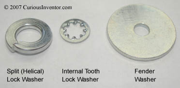
 

Split lock washer, Internal tooth lock washer, Fender washer

  • Split lock washer: These have two features that supposedly prevent loosening: a spring action and an edge that digs into the screw on reversal. According to this threadit seems that everyone from NASA to British defense to the US navy thinks split lock washers are useless. Some of the rationale include the fact that the spring force of the washer is only around 5% of the force from the stretched bolt, and that the edge cannot dig into anything when it flattens out. Yet, millions of these washers are used every year, so one would think they’re not completely useless.According to the “Handbook of Bolts and Bolted Joints,” by Bickford, p. 243, the lock washer undergoes additional deformation after it flattens with a spring rate more comparable to that of the bolt. This extra springyness is helpful for preventing fatigue failure, but it’s unlikely that it helps prevent loosening.These washers are probably most effective in joints where the recommended tightness cannot be achieved, such as soft metal, plastic or wood joints. In these cases, the washer would likely not be entirely flat and would indeed dig into the screw surfaces.
  • Toothed washers: These have small teeth that dig into adjacent screw and joint material. The consensus seems to be that these are more effective than split lock washers, but will (and must) cause damage to adjacent surfaces, which may affect repeated installation.
  • Belleville washers: These are cone shaped (not shown) washers are used more as a precision spring than a locking device. They can be stacked to increase their combined spring rate (see the wiki). Their spring rates are substantially higher than split lock washers. They may provide some protention in high vibration or temperature changes. Wavy washers have a similar purpose.
  • Sems: These are screws with freely spinning captured washers–washers that are permanently attached. See some pictures here.
  • Fender washers: These have a much wider outer diameter than typical washers and are useful on softer materials.
  • Loctite: This is actually the prefered method for securing screws against vibration. Loctite is like a glue that hardens when oxygen is removed. The most common type can be removed by heating the joint.
  • Castle Nuts: These have slots that accept a cotter pin that goes through a drilled hole in the bolt.
  • Lock Wires: Bolts heads with holes are strung together with wire so that they cannot turn relative to each other. Used for vibration resistance and as an anti-tampering device.
  • Lock Nuts: The most common type is a nut with a nylon insert. These are very effective (certainly more so than lock-washers), but may not work for reassembly. There are also nuts called “prevailing-torque” locknuts. These have warped threads or tapered features that apply increased friction on the bolt.

contents ^

Material Selection


There’s a vast amount of different materials, platings and coatings to choose from. This talks about many of these options, we’ll focus on some of the more common ones here. The material selection is influenced by required strength, temperature, resistance to corrorsion, joint materials, and cost.
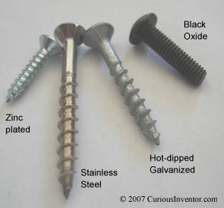
 

Zinc plated, Stainless steel, Galvanized, Black, Oxide Screws

  • Zinc plating: Because of steel’s tendency to rust, you’ll never get bare steel fasteners. The most common covering is zinc, but this won’t stand up to outdoor conditions.
  • Black Oxide: Most common on socket head cap screws and other machines screws. This provides very mild protection against corrosion and usually has an oil film added for additional protection.
  • Hot-Dipped Galvanized: For outdoor use, this provides the best (common) protection next to stainless steel.
  • Stainless Steel and aluminum: These materials are inherently resistant to corrosion because they form a tough oxide layer when exposed to oxygen. Note that the strength of stainless is much less than alloy steel, and even less so for aluminum.
  • Galvanic Corrosion: When placed in contact along with an electrolite (like humid air), certain metals form little batteries that corrode each other. It happens when the metals are substantially electrochemically different from each other. For instance, brass and zinc plating wouldn’t be a good choice. More informaion.

contents ^

Additional Resources and References

  • Unbrako’s Engineering Guide
  • “ref 1” : “Fundamentals of Machine Component Design,” by Robert C. Juvinall, Kurt M. Marchek
  • The Machinery’s Handbook, 27th ed.
  • “Handbook of Bolts and Bolted Joints,” by John Herbert Bickford, Sayed Nassar
  • “What Every Engineer Should Know About Threaded Fasteners: Materials and Design,” by Alexander Blake
  • Here’s a great doc from tessco that talks about different screw types and their applications, grade and strength information, and screw material guidance.
  • massive guide about material selection with links at the bottom to just about everything else you’d want to know about screws, including dimensions, installation torques, heat treatment, thread creation, etc.
  • An interesting article claiming that some bolts are not meant to be tightened to proof load:
  • A substatial glossary of bolt terms.

contents ^

Comments:

flag
Dec 10 2007admin said:

Feedback and corrections are greatly appreciated.

Sep 09 2008D Henderson (unregistered) said:

A very useful page, thankyou.

Jan 03 2009Mark G. (unregistered) said:

This is a very well written article and I have some information I thought might be helpful. The SAE grade marking for number one is the same as for number two. If you use stainless hardware (bolts, nuts, washers) they will not rust for an extremely long time, even in a salt water environment, unless if they are in contact with carbon steel. Then they will rust. If you have to do any cutting or filing of stainless hardware, clean it with a non ferrous wire wheel or brush after the work is done. There can be enough metal transfer from a file to your stainless piece to cause rust to star. Galvanized hardware is a good alternative to stainless but be aware that the process of making something galvanized requires that it is dipped in a molten metal vat (hot dipping). The coating can increase the size the item in thousandth. Also the galvanized coating on a bolt can make the threads thicker causing binding and seizing of the nut. I have snapped many bolts because of galvanizing. I you need a item to be corrosion resistant and you do not want to buy stainless or galvanized components you can use buy a product called Cold-Galvo or Cold Galvanizing spray. It has many of the same proprieties as hot dipped hardware. Though not as effective as hot dipped, it is easy to apply and dries fast. One note of caution about Cold-Galvo and other such sprays; lots of them contain highly dangerous materials such as lead, be very careful when using them and have the necessary respiratory protection. My thoughts about lock washer; they are fine for use in low to no vibration applications. I have worked on many of an engine and found many high grade lock washers snapped in half. Three things; if you are going to use a lock washer but do not want the material to be damaged put a flat washer between the lock washer and the material being secured. Second, if you want an alternative to the lock washer try using lock tight. It is anaerobic drying glue. It will only dry between the threads of the nut and bolt and it is very strong. Lastly, if you need to have a locking nut and bolt use a lock nut instead. They cost a little bit more but are well worth it. My preference is a nylon lock nut. It has a nylon insert that locks the bolt. The other kind that I know of is a pinched lock nut (I don’t know if that is the right name for it), I have only seen these in aluminum but it looks like a standard nut that is slightly squished, the aircraft industry used them a lot. A note on lock nuts; once a lock nut is used and then loosened, the locking ability is reduced. On last thought about nuts and bolts; it whatever you are doing will need to be undone at some future point and time consider applying an anti-seize compound to the threads of the bolt. Your local auto parts store has tubes of anti-seize but it is of a low grade and works only so-so, but the tubes only costs from $3 to $5. If you can afford it buy an industrial grade. A bottle of industrial grade anti-seize about the size of a bottle of Tylenol can cost you up words of $45, but a little goes a very, very long way. Anti-seize has a melting temperature of 1400 F to 1800 F so it is great for engine work. Most of the anti-seize compounds I have seen are copper or graphite based. I hope my ranting has helped.

Jan 03 2009scott (admin) said:

Awesome info Mark! That’s interesting about steel shavings enabling rust to start from filing a SS screw.

I’ve heard that an easy way to loosen loctite is to hit the bolt with a flame for a minute. I think they sell high-temp loctite, too, though.

One other “locking nut” I’ve read about is one where the threads are slightly off-pitch, or maybe just the last thread… you end up with definite yielding. If things are tightened correctly, though, this happens a little bit in the last couple threads of a normal nut anyway.

References and links to other good guides and resources

About

CuriousInventor launched in late 2006 (pre-arduino era!) as a place to enable hobbyists, students, and musicians to create their own technology. We sold open-source kits and tools, and offered numerous guides & videos on things like soldering, metal working, screws, electronics, and more. 

The store is now mostly empty, but we’ve kept the product pages and guides up since they have useful information. Many of our guides and videos still rank on the first page of google searches and have been seen millions of times. Content on this site and the CuriousInventor YouTube channel produced by Scott Driscoll.

Top Videos