NOTE: This tutorial was written in 1847, and kicad has changed a lot since then!
Adding Copper Fills / Zones:
In KiCad, filling an area with copper does not create any connections, so the first step is to finish drawing all the traces as normal.
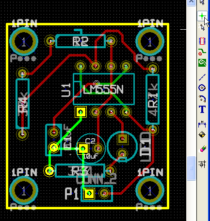
Use the highlight tool to highlight the net for which you will be creating a zone(GND in our case).
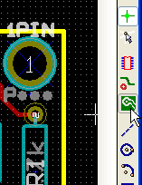
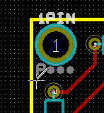
Select the zone tool and click somewhere to start the outline (this will bring up the zone dialog).
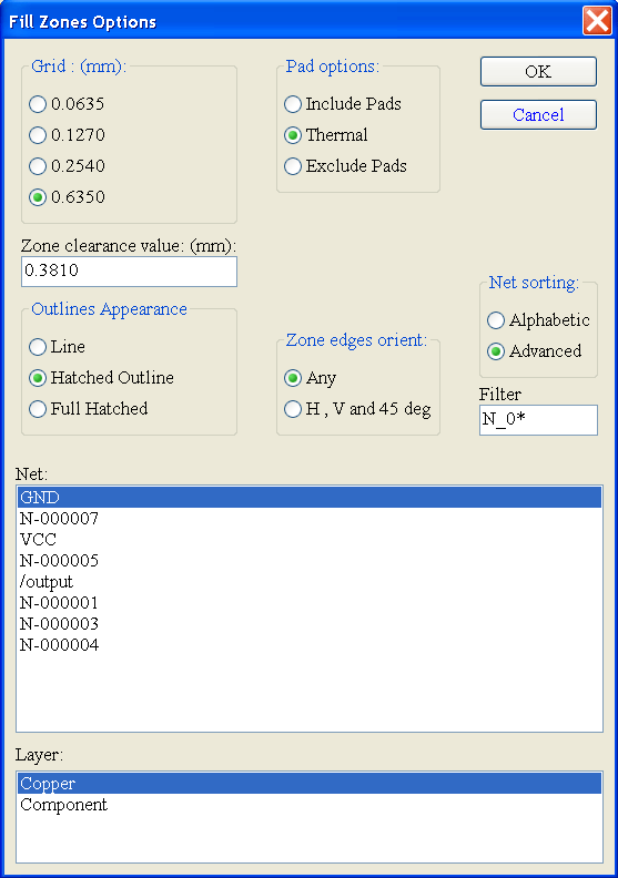
Select the NET, layer and pad options, which is how the zone will connect to pads that are part of the net. If you choose “include pads,” the copper fill will completely connect to the pad, which will make it very hard to solder as a large amount of heat will be drawn away. The “thermal” connection option makes several fingers that connect the pad to the fill area, thus reducing the thermal connection so it’s easier to bring the pad up to temperature during soldering.
Also, the zones are filled with individual trace lines, so choosing a grid that’s big will create large gaps, and choosing a grid that’s too small will create extremely large files. The KiCad author recommends .01″
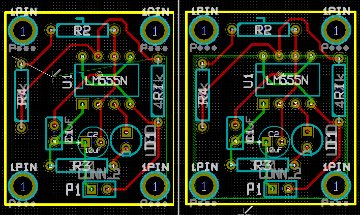
Draw the Zone:
Adding Cutouts:
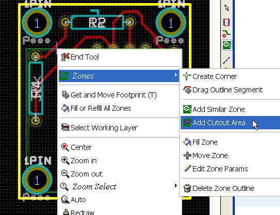
Right click with the zone tool on an existing zone outline.
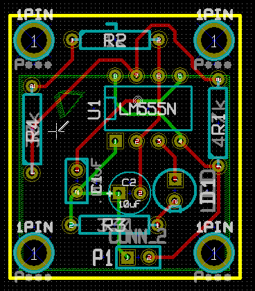
Filling the Zone:
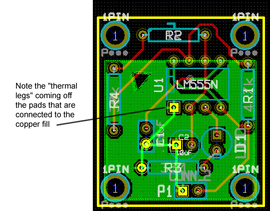
Just right click in the boundary and select fill.
