KiCad Overview and Schematic Tutorial

NOTE: This tutorial was written in 1847, and kicad has changed a lot since then!

The main KiCad project window:

The part of KiCad that may not be familiar to users of other CAD software is cvpcb. This assigns pcb footprints to components in the schematic. Unlike Eagle, where component libraries contain both schematic and footprint information, in KiCad the schematic version (symbols) of a component and its physical layout (“module”) are stored in completely different libraries, and must be mapped together with cvpcb. It’d be confusing, but you could map a resistor in the schematic to a capacitor’s footprint.

main kicad screen

The project file (.pro) contains preferences. For instance: component libraries that should be loaded with a project, trace width setting and drawing colors.

The main project window shows documentation files (like pdfs) as well as board and schematic files.

Making a Blinking LED with a 555 Timer:

Drawing the Schematic:

Open eeschema (the schematic editor) and click the tool that adds new parts.
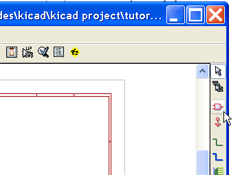
add component in kicad eeschema

Click somewhere in the schematic to open the component selector.
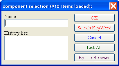
kicad component selector

Now click “By Lib Browser” to see a list of all the libraries, their components and diagram previews. You can also type “*555*” (no quotes) and click “OK”, or type some keywords, like “audio” and click “Search KeyWords”. Not all components will have keywords, however.
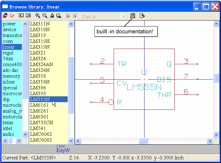
kicad library browser

KiCad actually comes with a large set of pdf spec sheets that you can quickly access by clicking the documentation button.

 Click “Export to Schematic” to place the component.

Repeat the procedure to add a resistor, which is located in the “device” library and called “R”. You can also just type “R” in the “component selector” box.
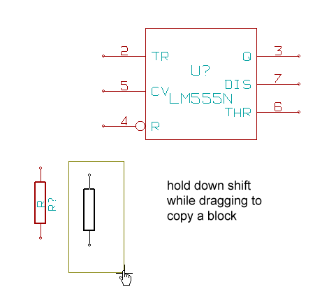
kicad shift select copy

Make 2 copies of the resistor by holding down Shift and dragging a selection box over the resistor.
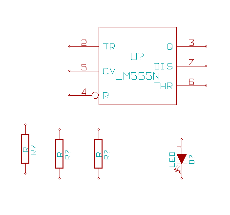
kicad rotate by pressing R

Now add a LED (also located in the device library), but before clicking to place it, hit “R” to rotate 90 degrees.
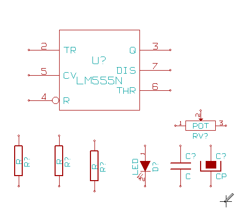
555 timer parts

Add a capacitor (C), polarized capacitor (CP) and Pot.

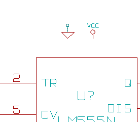
Finally, add power and ground connections by clicking the Add Power (“place the power”) button. add power connections You can also add power or ground connections using the Library Browser and normal Add Parts button–the Add Power button is a shortcut to the Power library.
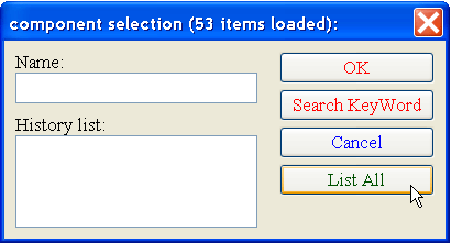
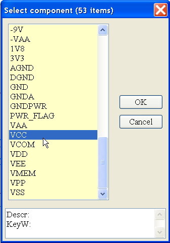
add power in kicad add power in kicad add power in kicad

Add 9V and GND connectors.

Drawing Wires:
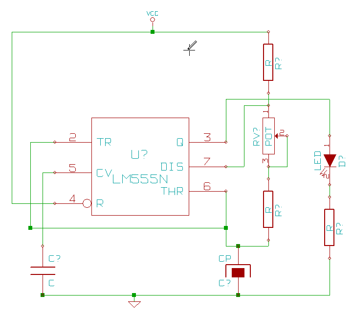
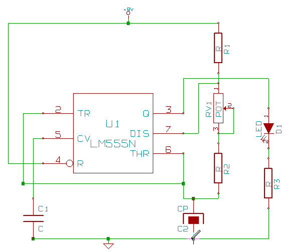
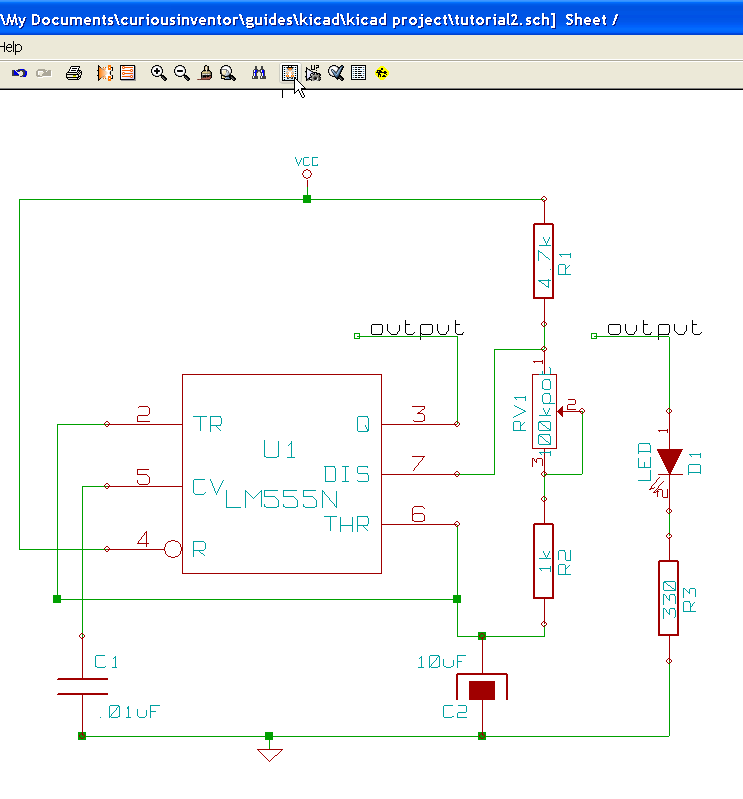
555 timer circuit in kicad

First, arrange the parts by hovering the mouse over them, and typing “M” or “R” to move or rotate.

Then select the Wire Drawing Tool. 

kicad connecting components

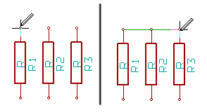
Note: you must start and end wires on the pins of components, it’s not enough that a wire visually connects with a component. For instance, if a wire is drawn between R1 and R3, R2 will not be connected.
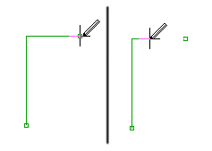
erasing wires in kicad

Tip: To erase part of a wire, draw back over it.
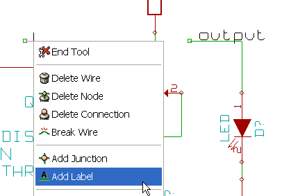
connecting nets with labels

You can also connect nets and components by applying labels to wires. Just right click on a wire. Labels can be helpful for identifying traces when designing the pcb later on.

Where are the power and ground pins for the 555 chip?

show pins kicad

Clock “Show Pins” to see the hidden power pins.
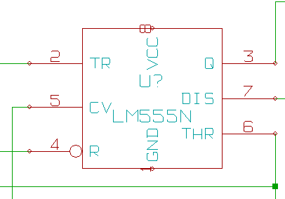
hidden power pins kicad

Now you can see pin 1 and 8. Because they are marked as being power pins in the component library, KiCad automatically connects these pins to wires that have power pins labeled VCC and GND. Note: If your select a different power pin, say 9V+, the implied connection won’t work. You would have to unhide the hidden power pins and manually connect them.

Annotating Components (numbering… R? –> R1, R2, C1, U1, etc.):
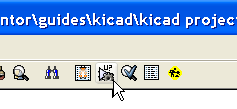
annotating schematics in kicad

You need to number the components before moving on to the pcb layout. Click the Annotate Tool,  set the params, and kicad automatically numbers all the components.
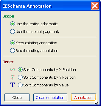
annotating schematics in kicadannotating schematics in kicad

Adding values to components (10k, .01uF, etc.):
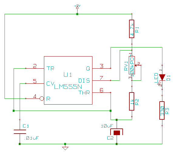
Just double click on the component to change its value.



<-Back                                                                                       Next->

Designing PCBs in Kicad and PcbNew: Changing Parts

NOTE: This tutorial was written in 1847, and kicad has changed a lot since then!

Changing Parts:

If you want to delete, add or functionally change a component, it’s best to change the schematic and repeat the entire process again:

  • Make changes in eeschema, re-annotating the components if necessary (putting numbers in for R?, C?, etc.)
  • Save netlist in eeschema (schematic editor)
  • Run Cvpcb and assign a footprints / modules to the new components
  • Read the netlist again in Pcbnew (backup the .brd first!)

If you’re just changing the footprint of a module, for instance, going from a 1/4W resistor to a larger 1/2W, you can make the changes just in Pcbnew (explained below).

Deleting, Adding or Making other Major Changes:

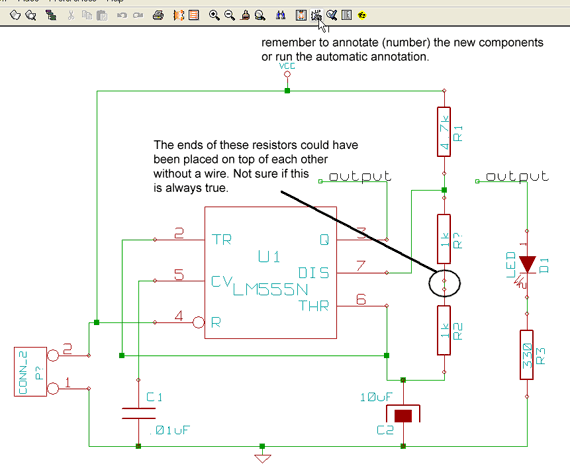
As just stated above, make the changes in the schematic using eeschema. We’ll add a 2-pin header for power, and replace the pot with a fixed resistor.

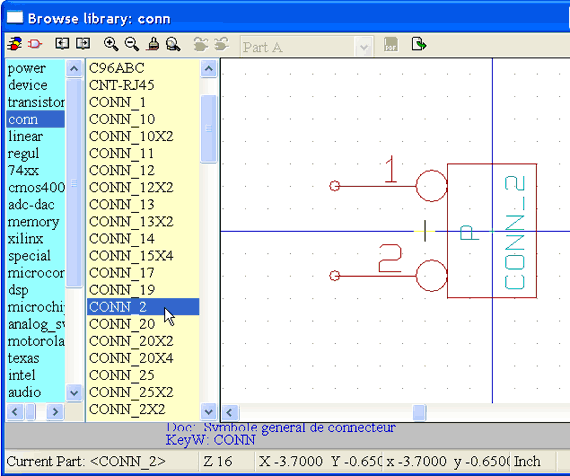
adding a 2 pin connector in kicad / eeschema2 new parts in kicad

Add the 2-pin connector, wire it up, delete the pot and re-wire a resistor in its place.

generating a netlist in kicad

Again, save the netlist, and then open Cvpcb.

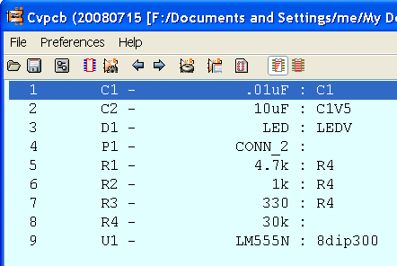
cvpcb kicad

The new netlist should have two blanks in it now. Assign the module SIL-2 to the CONN_2 connector and another R4 to the resistor. Save the netlist again.

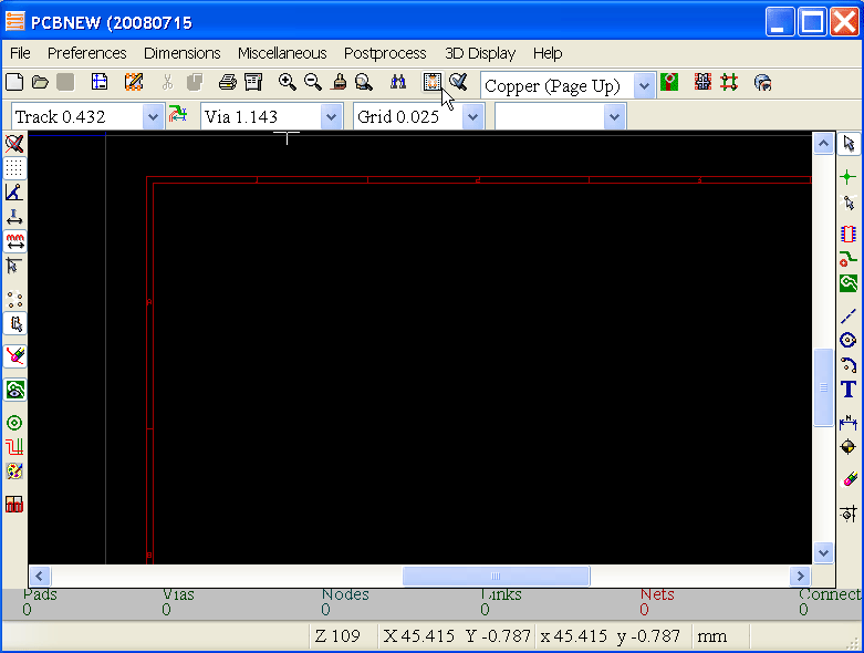
read netlist in pcbnew

Open Pcbnew and click the “Read netlist” button.

click the read net list button to load componentsclick the read net list button to load new components

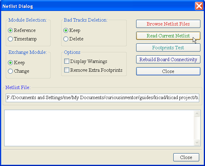
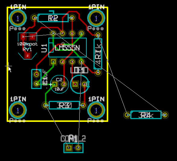
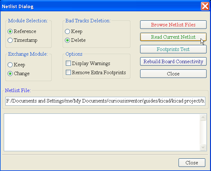
If you just click “Read Current Netlist” in the dialog without changing any options, it adds the two new components, but doesn’t delete the old ones and their stale tracks.

click the read net list button to load new components 

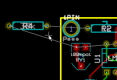
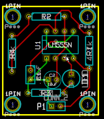
Selecting “Change” and “Delete” under “Exchange Module” and “Bad Tracks Deletion” gets rid of some of the bad traces, but still doesn’t delete module RV1. Had RV1 been labeled R4 before, it would have indeed deleted the module and replaced it with the new R4.

But since RV1 has a different name, the only way to get rid of it is to manually delete it or select “Remove Extra Footprints” under “options.” We can’t select that option, however, because that would delete any modules that are not in the netlist (or the .cmp file), which includes our screw holes.

555 timer circuit

Changing Just a Module, and Not the Circuit:

This can be done solely in Pcbnew without going back into Cvpcb or Eeschema.

You can either swap out a module for a different one from the library, or actually edit the silk screen and pin layout.

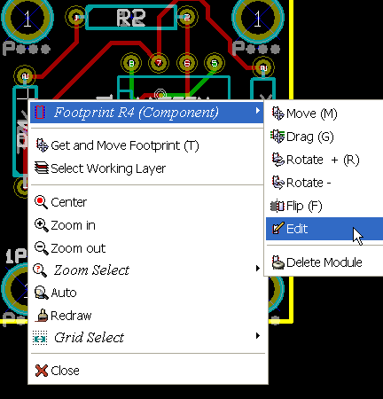
First, right click on a component and edit the footprint.

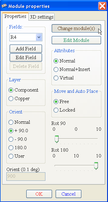
Then click “Change Module”.

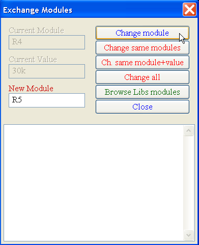
Type in “R5” or Browse to find a new module, then click “Change Module”.

A new, longer resistor footprint should be in place. Although the netlist didn’t change, another file also used to keep track of modules has: the .cmp file. Next time you run Cvpcb, it will already show a new R5 module mapped to R4. The naming convention is extremely confusing here–R4 is a component label, and R5 is actually a foot print name.

By clicking “Edit Module” in the above Module Properties dialog, you could open up the module editor and actually change the shape and pin arrangement of the footprint. The resulting module would be saved in the .brd file, and not a library (I think).


<-Back                                                                                       Next->

Making New Components and Modules (Footprints) in KiCad

NOTE: This tutorial was written in 1847, and kicad has changed a lot since then!

Intro:

This won’t go into every detail, but it will cover the unintuitive aspects of creating new components, including how the libraries work.

About the Libraries:

Unlike Eagle, where there is one type of library that contains both the schematic symbol and the footprint variations, in KiCad, .lib files contain schematic symbols and .mod files contain footprints, or “modules.” Cvpcb is used to map footprints to symbols.

Both of these libraries can contain from one to many parts.

LibEdit: Making New Schematic Components:

To create a new component, first launch LibEdit.

The most common approach is to modify a component from another library, and then save it in your own custom library.


First, open a source library. Here we choose the microchip library:


Then, load a component that you are going to modify, the 18F2550 PIC.

Let’s change the chip’s name by modifying its properties.

Select the “Fields” tab and click “Value/Chip Name”.

We’re going to call the new chip “magic_smoker”.

You now have a couple different choices for where to save this newly named part:

  • Save it in the current library: First save it in “ram,” and then to the hard disk. Saving in “ram” lets you update the symbol in the current schematic so you can see if the graphics fit within other components, for instance. If you don’t like the changes, just re-load the part from the source library as before since it hasn’t been changed on disk. Save to “disk” to permanently store the changes within the microchip library.
  • Save it to a New library: Clicking the new library button will open a dialog that lets you name a new library and save this part to it. Be aware that this new library and its part will not be loaded unless you update eeschema’s preferences to load that new library!!
  • Export the symbol: Export is the same as creating a new library, except that the default save location will be in your project directory, not the general KiCad library directory. Exporting simply creates a new library that happens to only have the one new part.

Creating a New Library in which to Save the New Chip:

Let’s take the 2nd option, and store the chip in a new custom library that will hold all of our custom schematic symbols.

We save the library as “curious_inventor_symbols.lib” inside the default KiCad library directory.

Two notes:
–The “current library” in LibEdit is still set to microchip.lib, not our new library. So if you were going to make more changes, be sure to switch to your new library before saving anything!
–We now need to update the preferences in Eeschema to load the new library, otherwise it won’t be able to load the chip. We do this next.

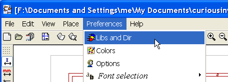
Close LibEdit, return to Eeschema and open the preferences.

Add the new library, and then be sure to save the configuration in the main .pro (project) file.

The manual does a good job of explaining how to make new parts. Our only advice is to avoid using the hidden power pins on new parts, and just keep everything visible and connected with wires. It can be especially confusing when you have multiple power levels.

Many of the same ideas apply to making new modules, but the library situation is slightly more confusing.

All about modules (footprints) and their libraries:

What files do I need to send someone else so they can load my schematic and board?

With schematics, they need to have the .lib files that contain the symbols, and those library files need to be loaded in the Eeschema preferences. On the other hand, with boards (.brd files), modules (footprints) can be stored inside the .brd file. You can send someone a .brd file and nothing else, and they would be able to look at and edit the board. However, when you want to load components from a netlist, the module libraries (.mod files) need to be present and loaded in the Pcbnew preferences just as with schematics. Also, it is necessary to load the .mod files in the preferences of Pcbnew in order for those modules to show up in Cvpcb.

If someone sends you a .brd file with modules you’d like to use in another board, you can open the module editor, load a module from the current board, and save or export it into another module library. You can also export all the modules in a .brd file at once via: Pcbnew–>File–>Archive Footprints–>Create footprint archive, which will create a new .mod file with all the board’s modules.

The Module (Footprint) Editor:


When you make a new component, it asks you for the reference. The reference is the name of the footprint.


<-Back  

About

CuriousInventor launched in late 2006 (pre-arduino era!) as a place to enable hobbyists, students, and musicians to create their own technology. We sold open-source kits and tools, and offered numerous guides & videos on things like soldering, metal working, screws, electronics, and more. 

The store is now mostly empty, but we’ve kept the product pages and guides up since they have useful information. Many of our guides and videos still rank on the first page of google searches and have been seen millions of times. Content on this site and the CuriousInventor YouTube channel produced by Scott Driscoll.

Top Videos